Section 18 Serial Sound Interface
Page 924 of 2108 R01UH0134EJ0400 Rev. 4.00
Sep 24, 2014
SH7262 Group, SH7264 Group
When this module acts as a transmitter, each word written to SSITDR is transmitted to the serial
audio bus in the order they are written. When this module acts as a receiver, each word received
by the serial audio bus is read in the order received from the SSIRDR register.
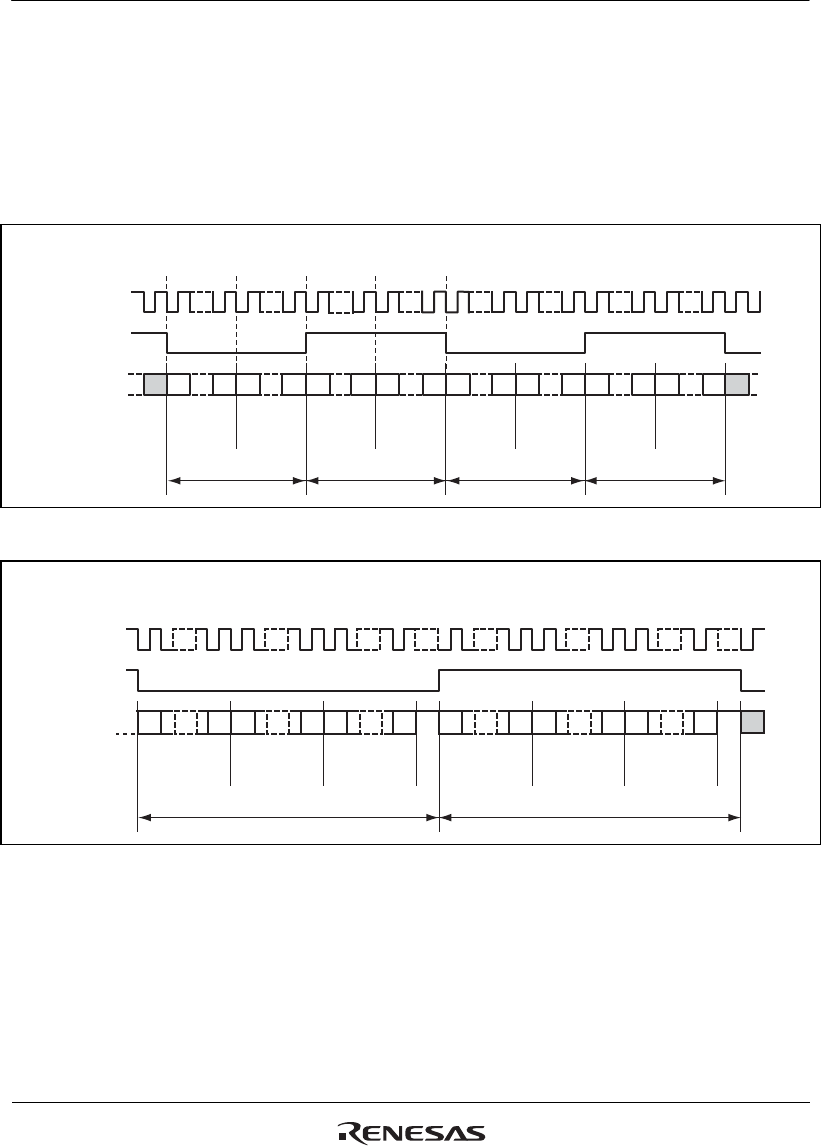
Figures 18.7 to 18.9 show how the data on 4, 6, and 8 channels are transferred to the serial audio
bus. Note that there are no padding bits in the first example, the second example is left-aligned and
the third is right-aligned. The other conditions in these examples have been selected arbitrarily.
MSB LSB
Data
word 1
MSB LSB MSB LSB MSB LSB
Data
word 2
Data
word 3
Data
word 4
System word 1 System word 2
MSB LSB
Data
word 1
MSB LSB MSB LSB MSB LSB
Data
word 2
Data
word 3
Data
word 4
System word 1
System word 2
LSB MSB
SSISCK
SSIWS
SSIDATA
SCKP = 0, SWSP = 0, DEL = 0, CHNL = 01, SPDP = don't care, SDTA = don't care
System word length = data word length × 2
Figure 18.7 Multi-Channel Format (4 Channels Without Padding)
MSB LSB
System word 2
Data
word 1
MSB LSB MSB LSB MSB
Data
word 2
Data
word 3
Padding
System word 1
MSB LSB MSB LSBMSB LSB
Data
word 4
Data
word 5
Data
word 6
SSISCK
SSIWS
SSIDATA
Padding
SCKP = 0, SWSP = 0, DEL = 0, CHNL = 10, SPDP = 1, SDTA = 0
System word length = data word length × 3
Figure 18.8 Multi-Channel Format (6 Channels with High Padding)


