Section 7 Interrupt Controller
Page 194 of 2108 R01UH0134EJ0400 Rev. 4.00
Sep 24, 2014
SH7262 Group, SH7264 Group
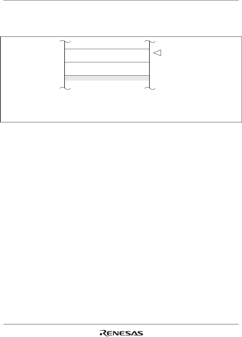
7.6.2 Stack after Interrupt Exception Handling
Figure 7.3 shows the stack after interrupt exception handling.
Address
SP*
2
4n – 8 PC*
1
SR
4n – 4
4n
32 bits
32 bits
Notes: 1. PC: Start address of the next instruction (return destination instruction)
after the executed instruction
2. Always make sure that SP is a multiple of 4.
Figure 7.3 Stack after Interrupt Exception Handling


