Section 15 Serial Communication Interface with FIFO
R01UH0134EJ0400 Rev. 4.00 Page 733 of 2108
Sep 24, 2014
SH7262 Group, SH7264 Group
Clock synchronous mode:
N = × 10
6
− 1
8 × 2
2n-1
× B
Pφ
B: Bit rate (bits/s)
N: SCBRR setting for baud rate generator (0 N 255)
(The setting must satisfy the electrical characteristics.)
P: Operating frequency for peripheral modules (MHz)
n: Baud rate generator clock source (n 0, 1, 2, 3) (for the clock sources and values of n,
see table 15.3.)
Table 15.3 SCSMR Settings
SCSMR Settings
n Clock Source CKS[1] CKS[0]
0 P 0 0
1 P/4 0 1
2 P/16 1 0
3 P/64 1 1
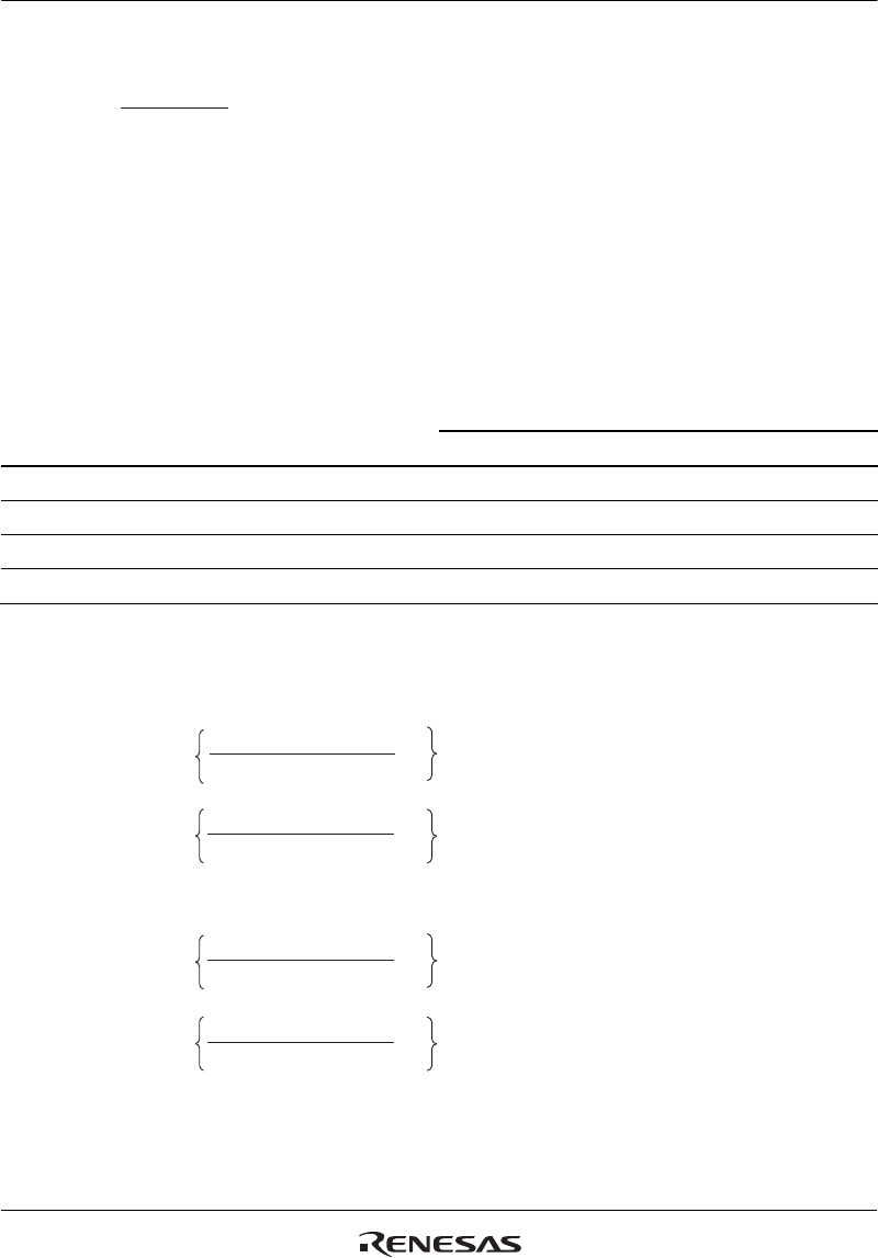
The bit rate error in asynchronous mode is given by the following formula:
Error (%) =
Error (%) =
Error (%) =
Error (%) =
− 1
− 1
− 1
− 1
× 100 (Operation on a base clock with a frequency of
16 times the bit rate)
× 100 (Operation on a base clock with a frequency of
8 times the bit rate)
× 100 (Operation on a base clock with a frequency of
16 times the bit rate)
× 100 (Operation on a base clock with a frequency of
8 times the bit rate)
(N + 1) × B × 64 × 2
2n-1
(N + 1) × B × 32× 2
2n-1
(N + 1) × B × 32× 2
2n-1
(N + 1) × B × 16× 2
2n-1
Pφ × 10
6
Pφ × 10
6
Pφ × 10
6
Pφ × 10
6
When baud rate generator operates in normal mode (the BGDM bit of SCEMR is 0):
When baud rate generator operates in double speed mode (the BGDM bit of SCEMR is 1):


