Section 11 Multi-Function Timer Pulse Unit 2
R01UH0134EJ0400 Rev. 4.00 Page 447 of 2108
Sep 24, 2014
SH7262 Group, SH7264 Group
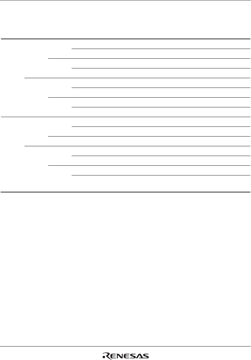
Table 11.10 Setting of Operation Mode by Bits MD0 to MD3
Bit 3
MD3
Bit 2
MD2
Bit 1
MD1
Bit 0
MD0
Description
0 0 0 0 Normal operation
1 Setting prohibited
1 0 PWM mode 1
1 PWM mode 2*
1
1 0 0 Phase counting mode 1*
2
1 Phase counting mode 2*
2
1 0 Phase counting mode 3*
2
1 Phase counting mode 4*
2
1 0 0 0 Reset synchronous PWM mode*
3
1 Setting prohibited
1 X Setting prohibited
1 0 0 Setting prohibited
1 Complementary PWM mode 1 (transmit at crest)*
3
1 0 Complementary PWM mode 2 (transmit at trough)*
3
1 Complementary PWM mode 2 (transmit at crest and
trough)*
3
[Legend]
X: Don't care
Notes: 1. PWM mode 2 cannot be set for channels 3 and 4.
2. Phase counting mode cannot be set for channels 0, 3, and 4.
3. Reset synchronous PWM mode, complementary PWM mode can only be set for
channel 3. When channel 3 is set to reset synchronous PWM mode or complementary
PWM mode, the channel 4 settings become ineffective and automatically conform to the
channel 3 settings. However, do not set channel 4 to reset synchronous PWM mode or
complementary PWM mode. Reset synchronous PWM mode and complementary PWM
mode cannot be set for channels 0, 1, and 2.


