Section 21 IEBus
TM
Controller
R01UH0134EJ0400 Rev. 4.00 Page 1137 of 2108
Sep 24, 2014
SH7262 Group, SH7264 Group
21.4.2 Reception Format
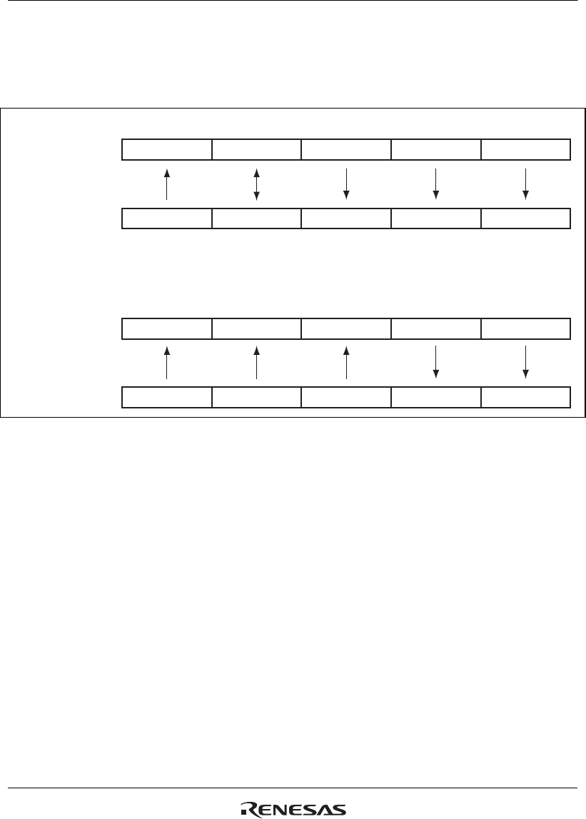
Figure 21.7 shows the relationship between the transfer format and each register during the IEBus
data reception.
Note: * Received slave address is compared with IEAR1 and IEAR2. If they match,
the subsequent operations are performed.
IERBFLIERCTL
[In slave reception]
[In master reception]
Communications frame
Communications frame
Register
Register
IERB001 to IERB128
Message length bits
Data bitsSlave addressMaster address Control bits
Message length bits
Data bitsSlave addressMaster address Control bits
IEAR1, IEAR2
IEMA1, IEMA2
IERBFLIEMCR
IERB001 to IERB128
IESA1, IESA2IEAR1, IEAR2
(*)
Figure 21.7 Relationship between Transfer Format and Each Register during IEBus Data
Reception


