Section 38 States and Handling of Pins
R01UH0134EJ0400 Rev. 4.00 Page 2047 of 2108
Sep 24, 2014
SH7262 Group, SH7264 Group
Section 38 States and Handling of Pins
38.1 Pin States
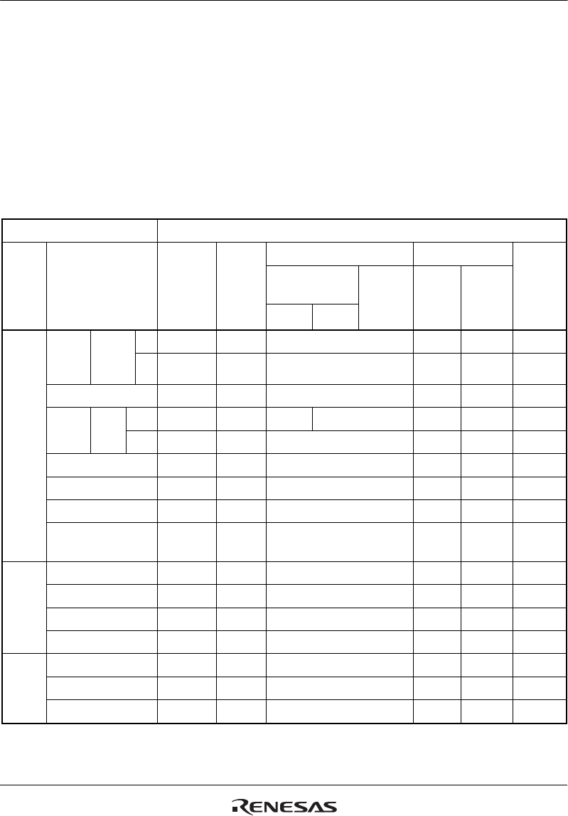
Table 38.1 shows the pin states in each operating mode.
As for the input/output functions, input buffers are listed on the upper column and output buffers
on the lower column.
Table 38.1 Pin States
Pin Function Pin State
Type Pin Name
Normal State
(Other than
States at
Right)
Power-On
Reset*
1
Pin State Retained*
2
Power-Down State
Bus
Mastership
Release
EBUSKEEPE*
3
(Other
than States at Right)
Power-On
Reset*
4
Deep
Standby
Mode
Software
Standby
Mode
0 1
Clock EXTAL*
6
Clock
operation
mode
0, 2 I I I I/Z*
5
I I
1, 3 Z Z Z Z Z Z
XTAL*
6
O O O O/L*
5
O/L*
5
O
CKIO Boot
mode
0 O/Z*
7
O O O/Z*
7
O/Z*
7
O/Z*
7
O/Z*
7
Other O/Z*
7
O O/Z*
7
O/Z*
7
O/Z*
7
O/Z*
7
AUDIO_CLK I Z Z I
AUDIO_X1*
6
I/Z*
8
I I Z Z I/Z*
8
AUDIO_X2*
6
O/L*
8
O O L L O/L*
8
AUDIO_XOUT (640-Kbyte
only)
O/L*
8
O/Z*
9
*
16
O/Z*
9
*
16
L/Z*
9
O
System
control
RES I I I I I I
WDTOVF O H H H O
BREQ I Z Z I
BACK O Z Z Z L
Operation
mode
control
MD_BOOT1, MD_BOOT0 I
MD_CLK1, MD_CLK0 I
ASEMD I I I I I I


