Section 11 Multi-Function Timer Pulse Unit 2
R01UH0134EJ0400 Rev. 4.00 Page 615 of 2108
Sep 24, 2014
SH7262 Group, SH7264 Group
TCNT3
TCNT4
TGRA_3
TGR
TDDR
0
Synchronous clearing
Dead time
Note: PWM output is low-active.
PWM output
(positive phase)
PWM output
(negative phase)
Initial output suppression
Tb interval Tb interval
(10) (10)(11) (11)
Active-level output occurs at synchronous clearing
even though no active-level output interval has been set.
Nonexistent
dead time
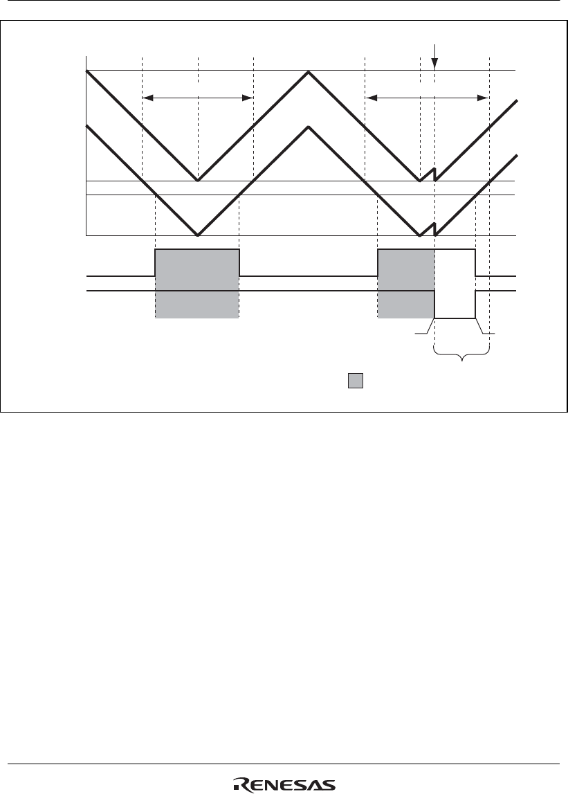
Figure 11.114 Condition (2) Synchronous Clearing Example
The following workaround can be used to avoid these problems.
When using synchronous clearing, make sure to set compare registers TGRB_3, TGRA_4, and
TGRB_4 to a value twice or more the setting of dead time data register TDDR.


