


8 - 11
8. CALCULATION METHODS FOR DESIGNING
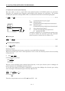
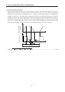
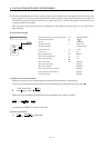
(2) Set the end (OFF position) of the actuator signal at the middle of two ON positions (Lows) of the zero
pulse signal. If it is set near either ON position of the zero pulse signal, the positioning unit is liable to
misdetect the zero pulse signal. In this case, a fault will occur, e.g. the home position will shift by one
revolution of the servo motor.
The zero pulse output position can be confirmed by OP (encoder Z-phase pulse) on the external I/O
signal display.
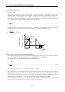
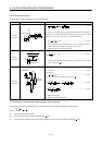
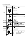
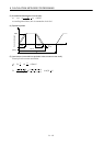
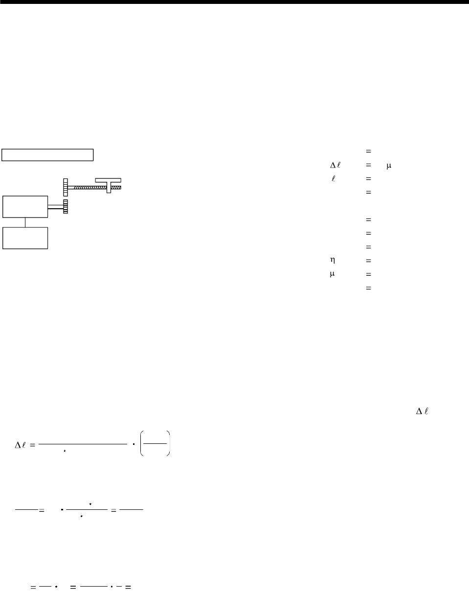
8.10 Selection example
Speed of moving part during fast feed V0 30000[mm/min]
Command resolution 10[ m]
Travel 400[mm]
Positioning time t
0 within 1[s]
Number of feeds 40[times/min]
Operation cycle tf
1.5[s]
Gear ratio n
8/5
Moving part mass W
60[kg]
Drive system efficiency 0.8
Friction coefficient
0.2
Ball screw lead Pb 16[mm]
Ball screw diameter 20[mm]
Ball screw length 500[mm]
Gear diameter (servo motor) 25[mm]
Gear diameter (load shaft) 40[mm]
Machine specifications
Servo
motor
Servo
amplifier
Gear ratio 5:8
Gear face width 10[mm]
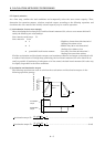
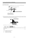
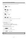
(1) Selection of control parameters
Setting of electronic gear (command pulse multiplication numerator, denominator)
There is the following relationship between the multiplication setting and travel per pulse
.
8192 (gear ration)
(ball screw lead)
CDV
CMX
When the above machining specifications are substituted in the above equation:
CDV
CMX
10
16 1000
8192 8/5
1000
8192
Acceptable as CMX/CDV is within 1/20 to 20.
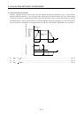
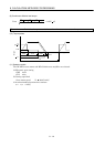
(2) Servo motor speed
No
Pb
V
0
n
16
30000
5
8
3000[r/min]