


8 - 8
8. CALCULATION METHODS FOR DESIGNING
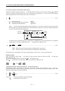
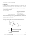
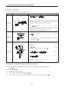
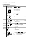
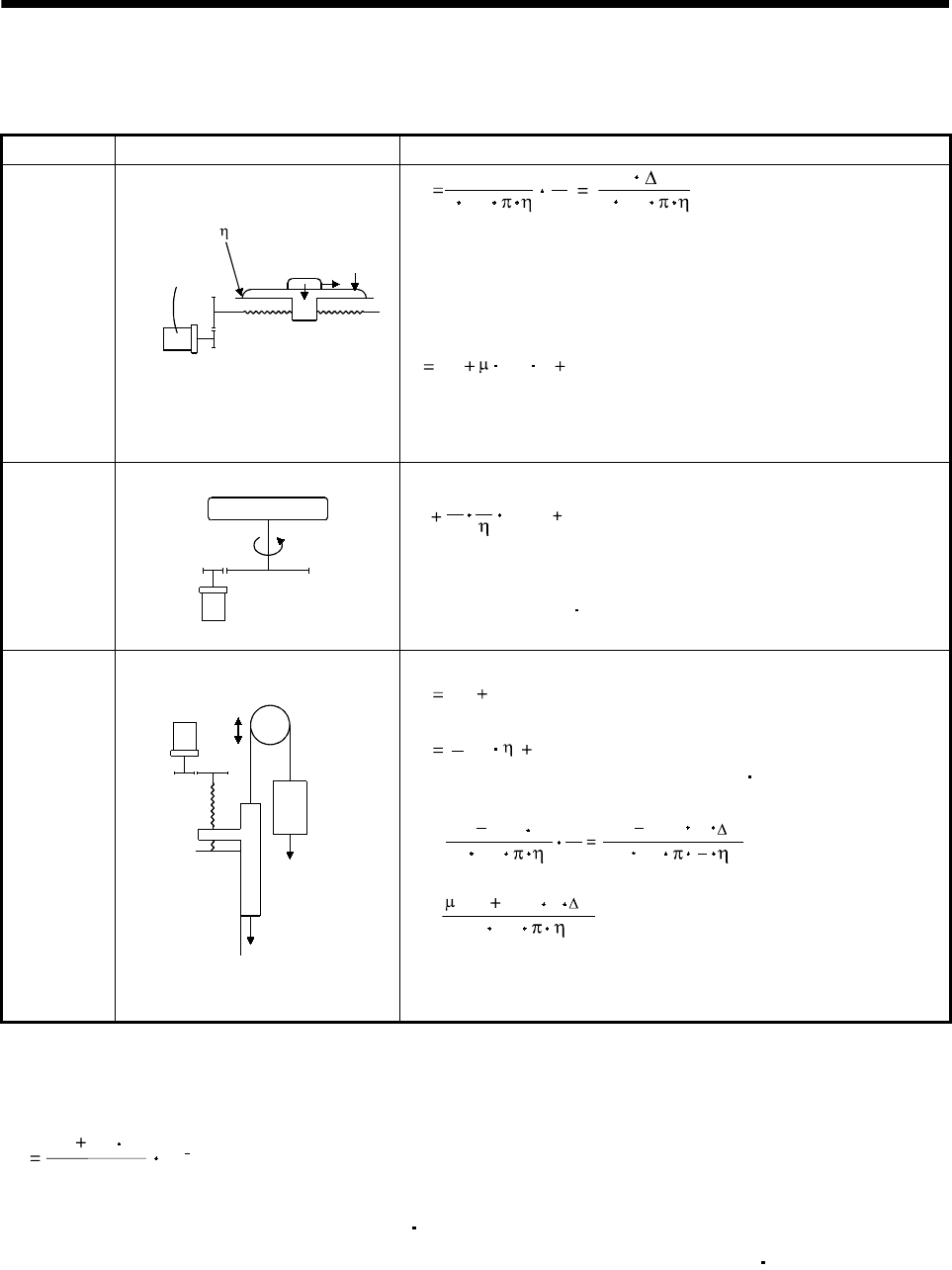
8.6 Load torque equations
Typical load torque equations are indicated below:
Type Mechanism Equation
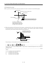
Linear
movement
Servo motor
W
Z
1
F
C
F
G
Z
2
TL
210
3
F
N
V
210
3
F S
......................................(8.15)
F : Force in the axial direction of the machine in linear motion [N]
F in Equation 15.9 is obtained with Equation 8.16 when the table
is moved, for example, as shown in the left diagram.
F Fc (W g FG) ........................................................(8.16)
Fc : Force applied in the axial direction of the moving part [N]
F
G : Tightening force of the table guide surface [N]
W : Full mass of the moving part [kg]
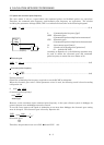
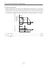
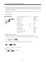
Rotary
movement
Servo motor
Z
1
Z
2
T
L0
TL
n
1
1
T
L0
T
F
...........................................................(8.17)
T
F : Load friction torque converted into equivalent value on servo
motor shaft [N
m]
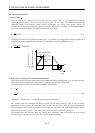
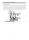
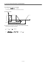
Vertical
movement
Counter
weight
Servo motor
W
2
W
1
1/n
Load
Guide
During rise
T
L TU TF .........................................................................(8.18)
During fall
TL TU
2
TF ................................................................(8.19)
T
F: Friction torque of the moving part [N m]
T
U =
10
(W
1
W
2
)
N
V
g
S
(W
1
W
2
)
g
2
3
210
3
...........................(8.20)
T
F =
10
3
2
g
(W
1
W
2
)
S
.........................................................(8.21)
W
1: Mass of load [kg]
W
2: Mass of counterweight [kg]
8.7 Expression for calculating the electromagnetic brake workload
Calculate the brake workload Eb [J] at an emergency stop with the following expression.
182
(J
M
J
L
)
N
2
Eb
10
4
N: Servo motor speed [r/min]
J
M: Servo motor's rotor inertia moment [kg cm
2
]
J
L: Load inertia moment converted into equivalent value on servo motor shaft [kg cm
2
]