


7 - 61
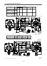
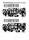
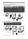
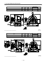
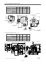
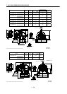
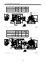
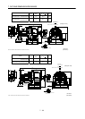
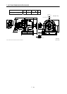
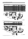
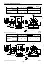
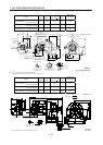
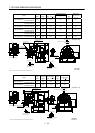
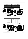
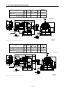
7. OUTLINE DIMENSION DRAWINGS
Model
Output
[kW]
Reduction
Ratio
Inertia Moment
J[
10
4
kg m
2
]
Mass
[kg]
HC-SF702G1H
HC-SFS702G1H
HC-SFS7024G1H
7.0 1/43 256.8 261
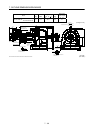
Power supply connector layout
CE05-2A32-17P
150
820
330
135
81.5
A
A
Motor plate
19.5
81.5
465
9
250
35
90
240
240
530
14
Motor flange direction
25
U
V
W
C
D
B
A
Earth
Section A-A
170
30
190
190
440
M20 threads, depth 34
Encoder connector
MS3102A20-29P
Power supply
connector
CE05-2A
32-17P
39.5
210
For reverse
rotation command
For forward
rotation command
"Rotation direction"
(Note)[Unit: mm]
[Side view of motor only]
Bottom Top
BC10755*
176
95h6
4- 26
430
(BC11809*)
Note: The dimensions without tolerances are reference dimensions.