


7 - 231
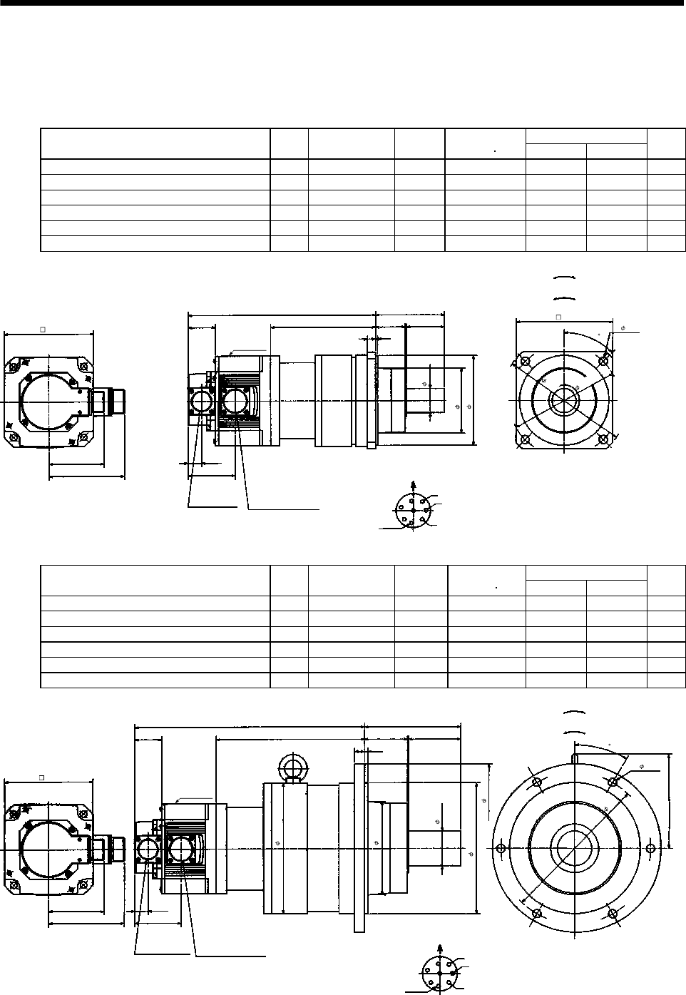
7. OUTLINE DIMENSION DRAWINGS
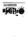
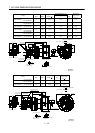
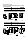
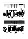
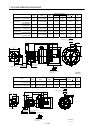
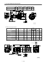
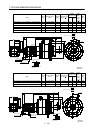
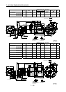
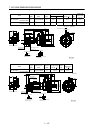
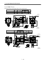
(5) With reduction gear for precision application
The outer frame of the reduction gear is a material surface such as casting. Its actual dimensions may
be 0.039 to 0.118 in larger than the drawing dimensions. Design the machine side with allowances.
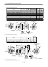
(a) Without electromagnetic brake
Variable Dimensions [in]
Model
Output
[kW]
Reduction Gear
Model
Reduction
Ratio
Inertia Moment
WK
2
[oz in
2
]
LH
Mass
[lb]
HC-SF52G2 HC-SFS52G2 HC-SFS524G2 0.5 BL2-05B-05MEH 1/5 43.19 10.87 6.14 28.7
HC-SF52G2 HC-SFS52G2 HC-SFS524G2 0.5 BL2-09B-05MEH 1/9 41.28 11.34 6.61 28.7
HC-SF52G2 HC-SFS52G2 HC-SFS524G2 0.5 BL2-20B-05MEH 1/20 43.88 12.17 7.44 33.1
HC-SF102G2 HC-SFS102G2 HC-SFS1024G2 1.0 BL2-05B-10MEH 1/5 81.88 11.85 6.14 33.1
HC-SF102G2 HC-SFS102G2 HC-SFS1024G2 1.0 BL2-09B-10MEH 1/9 79.96 12.32 6.61 33.1
HC-SF152G2 HC-SFS152G2 HC-SFS1524G2 1.5 BL2-05B-15MEH 1/5 116.05 12.84 6.14 37.5
0.77
W
V
U
L
2.17
3.94
A
F
G
H
B
E
C
D
5.12
4.37
3.21
2.70
1.56
H
1.69
0.47
0.12
1.38
3.70
5.12
4- 0.47
5.51
Z695320*
MS3102A20-29P
CE05-2A22-23P
Bottom Top
Encoder connector
Power supply connector
Motor flange direction
Earth
Power supply connector layout
CE05-2A22-23P
[Unit: in]
Motor plate
[Side view of motor only]
"Rotation direction"
For reverse
rotation command
For forward
rotation command
6
.
3
0
7
.
2
8
(BC11849*)
4
5
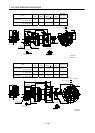
Variable Dimensions [in]
Model
Output
[kW]
Reduction Gear
Model
Reduction
Ratio
Inertia Moment
WK
2
[oz in
2
]
LH
Mass
[lb]
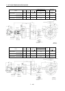
HC-SF52G2 HC-SFS52G2 HC-SFS524G2 0.5 BL3-29B-05MEH 1/29 51.39 13.27 8.54 66.1
HC-SF52G2 HC-SFS52G2 HC-SFS524G2 0.5 BL3-45B-05MEH 1/45 46.06 13.50 8.78 66.1
HC-SF102G2 HC-SFS102G2 HC-SFS1024G2 1.0 BL3-20B-10MEH 1/20 100.46 14.25 8.54 70.5
HC-SF102G2 HC-SFS102G2 HC-SFS1024G2 1.0 BL3-29B-10MEH 1/29 90.08 14.25 8.54 70.5
HC-SF152G2 HC-SFS152G2 HC-SFS1524G2 1.5 BL3-09B-15MEH 1/9 134.77 14.92 8.23 75.0
HC-SF152G2 HC-SFS152G2 HC-SFS1524G2 1.5 BL3-20B-15MEH 1/20 134.64 15.24 8.54 75.0
0.77
W
V
U
L
2.95
5.51
A
F
G
H
B
E
C
D
5.12
4.37
3.21
2.70
1.56
H
2.48
0.59
0.20
1.97
7.48
9.65
6- 0.47
5.32
8
.
6
6
5.39
7.48
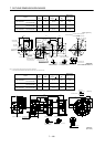
Z695321A
MS3102A20-29P
CE05-2A22-23P
Bottom Top
Encoder connector
Power supply connector
Motor flange direction
Earth
Power supply connector layout
CE05-2A22-23P
[Unit: in]
Motor plate
[Side view of motor only]
"Rotation direction"
For reverse
rotation command
For forward
rotation command
(BC11850*)
3
0