


7 - 90
7. OUTLINE DIMENSION DRAWINGS
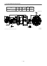
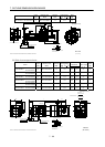
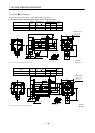
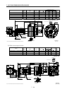
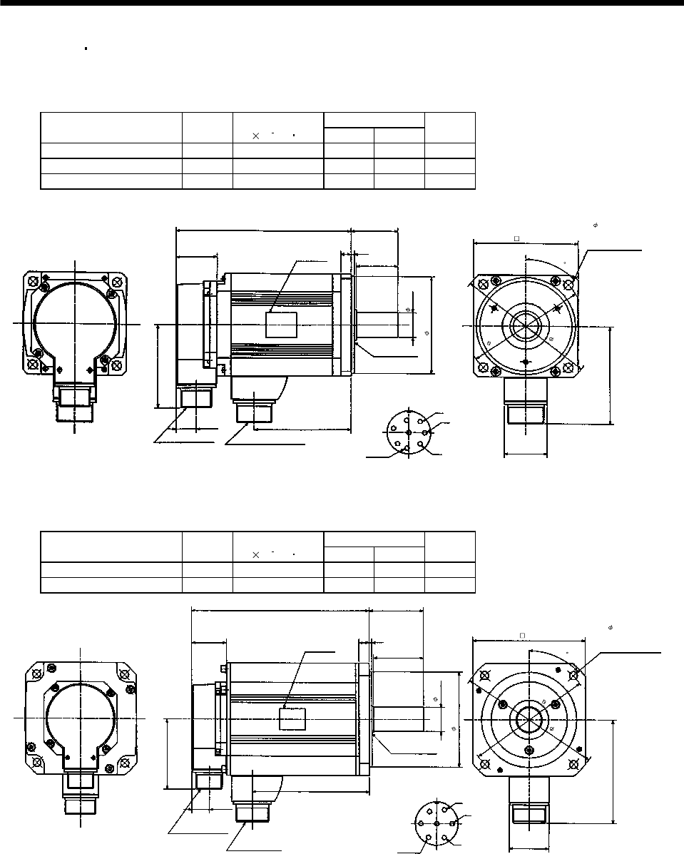
7.1.4 HC-RF HC-RFS series
If the above indicated value is exceeded, please consult us.
(1) Standard (without electromagnetic brake, without reduction gear)
Variable Dimensions
Model
Output
[kW]
Inertia Moment
J[
10
4
kg m
2
]
LKL
Mass
[kg]
HC-RF103 HC-RFS103 1.0 1.5 147 71 3.9
HC-RF153 HC-RFS153 1.5 1.9 172 96 5.0
HC-RF203 HC-RFS203 2.0 2.3 197 121 6.2
41
96
4
5
81.5
19.5
MS3102A20-29P
CE05-2A22-23P
W
V
U
A
F
G
H
B
E
C
D
KL
L
39.5
10
3
40
S30457B
24h6
45
Bottom
Top
Encoder connector
Power supply connector
Oil seal
Motor flange direction
Earth
Power supply connector layout
CE05-2A22-23P
(Note)[Unit: mm]
Use hexagon socket
head cap screw.
Motor plate
(Opposite side)
Bottom
Top
95h7
1
1
5
1
3
5
100
4- 9 mounting hole
Z694853*
(BC11697*)
Note: The dimensions without tolerances are reference dimensions.
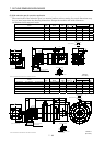
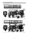
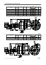
Variable Dimensions
Model
Output
[kW]
Inertia Moment
J[
10
4
kg m
2
]
LKL
Mass
[kg]
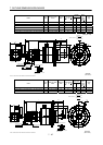
HC-RF353 HC-RFS353 3.5 8.6 217 148 12
HC-RF503 HC-RFS503 5.0 12.0 274 205 17
(Note)[Unit: mm]
58
Motor plate
Earth
V
U
W
D
C
B
A
G
F
E
120
Power supply connector layout
CE05-2A24-10P
Motor flange direction
3
63
12
39.5
28h6
Top
Bottom
L
(Opposite side)
Oil seal
S30457B
Bottom
Top
81.5
19.5
46
KL
Power supply connector
CE05-2A24-10P
Encoder connector
MS3102A20-29P
110h7
1
6
5
1
4
5
4- 9 mounting hole
Use hexagon socket
head cap screw.
130
Z695780*
4
5
(BC11698*)
Note: The dimensions without tolerances are reference dimensions.