


7 - 217
7. OUTLINE DIMENSION DRAWINGS
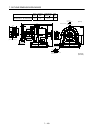
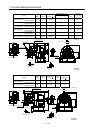
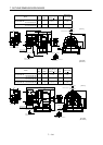
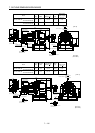
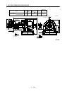
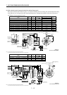
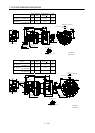
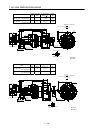
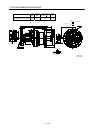
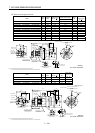
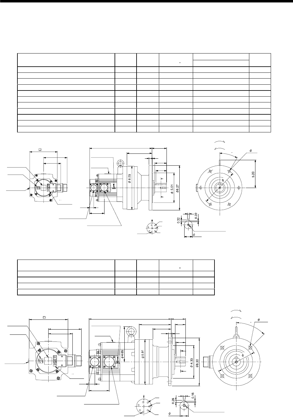
(4) With reduction gear for general industrial machine (flange type)
The outer frame of the reduction gear is a material surface such as casting. Its actual dimensions may
be 0.039 to 0.118 in larger than the drawing dimensions. Design the machine side with allowances.
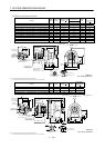
(a) Without electromagnetic brake
Variable Dimensions [in]
Model
Output
[kW]
Reduction
Ratio
Inertia Moment
WK
2
[oz in
2
]
L
Mass
[lb]
HC-SF52G1 HC-SFS52G1 HC-SFS524G1 0.5 1/35 41.01 10.59 59.5
HC-SF52G1 HC-SFS52G1 HC-SFS524G1 0.5 1/43 40.73 10.59 59.5
HC-SF52G1 HC-SFS52G1 HC-SFS524G1 0.5 1/59 40.60 10.59 59.5
HC-SF102G1 HC-SFS102G1 HC-SFS1024G1 1.0 1/6 91.85 11.58 63.9
HC-SF102G1 HC-SFS102G1 HC-SFS1024G1 1.0 1/11 83.7 11.58 63.9
HC-SF102G1 HC-SFS102G1 HC-SFS1024G1 1.0 1/17 81.47 11.58 63.9
HC-SF102G1 HC-SFS102G1 HC-SFS1024G1 1.0 1/29 79.83 11.58 63.9
HC-SF102G1 HC-SFS102G1 HC-SFS1024G1 1.0 1/35 79.8 11.58 63.9
HC-SF152G1 HC-SFS152G1 HC-SFS1524G1 1.5 1/6 126.3 12.56 68.3
HC-SF152G1 HC-SFS152G1 HC-SFS1524G1 1.5 1/11 117.55 12.56 68.3
HC-SF152G1 HC-SFS152G1 HC-SFS1524G1 1.5 1/17 115.9 12.56 68.3
3.21
4.37
A
B
C
D
E
F
G
H
Z695743*
BC11811B BC29695A
0.39
A
A
2.17
0.16
0.51
4.61
1.97
0.77
2.70
2.72L
Encoder connector
Power supply connector
V
U
CE05-2A22-23P
MS3102A20-29P
W
Motor plate
Caution plate
Caution plate
(Note 2)
(Opposite side)
1.50
5.12
Caution plate
Logo plate
(Note 2)
Side view of motor only
6- 0.43
Section AA
Power supply connector layout
Top
Bottom
Top
Bottom
Top
Bottom
TopBottom
For forward rotation command
"Rotation direction"
For reverse rotation command
Earth
CE05-2A22-23P
M8 screw, depth 0.79
Motor flange direction
TUV plate
7
.
0
9
3
0
(Note 1)[Unit: in]
Note 1. The dimensions without tolerances are reference dimensions.
2. This caution plate is attached to the 400V class motors only, not to the 200V class.
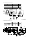
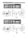
Model
Output
[kW]
Reduction
Ratio
Inertia Moment
WK
2
[oz in
2
]
Mass
[lb]
HC-SF52G1 HC-SFS52G1 HC-SFS524G1 0.5 1/6 40.05 40.8
HC-SF52G1 HC-SFS52G1 HC-SFS524G1 0.5 1/11 38.00 40.8
HC-SF52G1 HC-SFS52G1 HC-SFS524G1 0.5 1/17 37.45 40.8
HC-SF52G1 HC-SFS52G1 HC-SFS524G1 0.5 1/29 37.04 40.8
4.37
3.21
0.77
2.70
2.44
4.25
10.9
1.89
0.35
0.12
1.38
0.32
A
A
Z695742*
BC11810B BC26736A
A
B
C
D
E
F
G
H
1.26
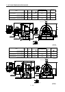
Encoder connector
Power supply connector
V
U
CE05-2A22-23P
MS3102A20-29P
W
Motor plate
Caution plate
Caution plate (Note 2)
(Opposite side)
1.10
5.12
Caution plate
Logo plate
(Note 2)
Side view of motor only
4- 0.43
Section AA
Power supply connector layout
Top
Bottom
TopBottom
Top
Bottom
Top
Bottom
For forward rotation command
"Rotation direction"
For reverse rotation command
Earth
CE05-2A22-23P
M8 screw, depth 0.79
Motor flange direction
TUV plate
4
5
5
.
2
8
(Note 1)[Unit: in]
Note 1. The dimensions without tolerances are reference dimensions.
2. This caution plate is attached to the 400V class motors only, not to the 200V class.