


7 - 32
7. OUTLINE DIMENSION DRAWINGS
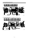
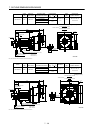
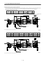
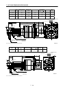
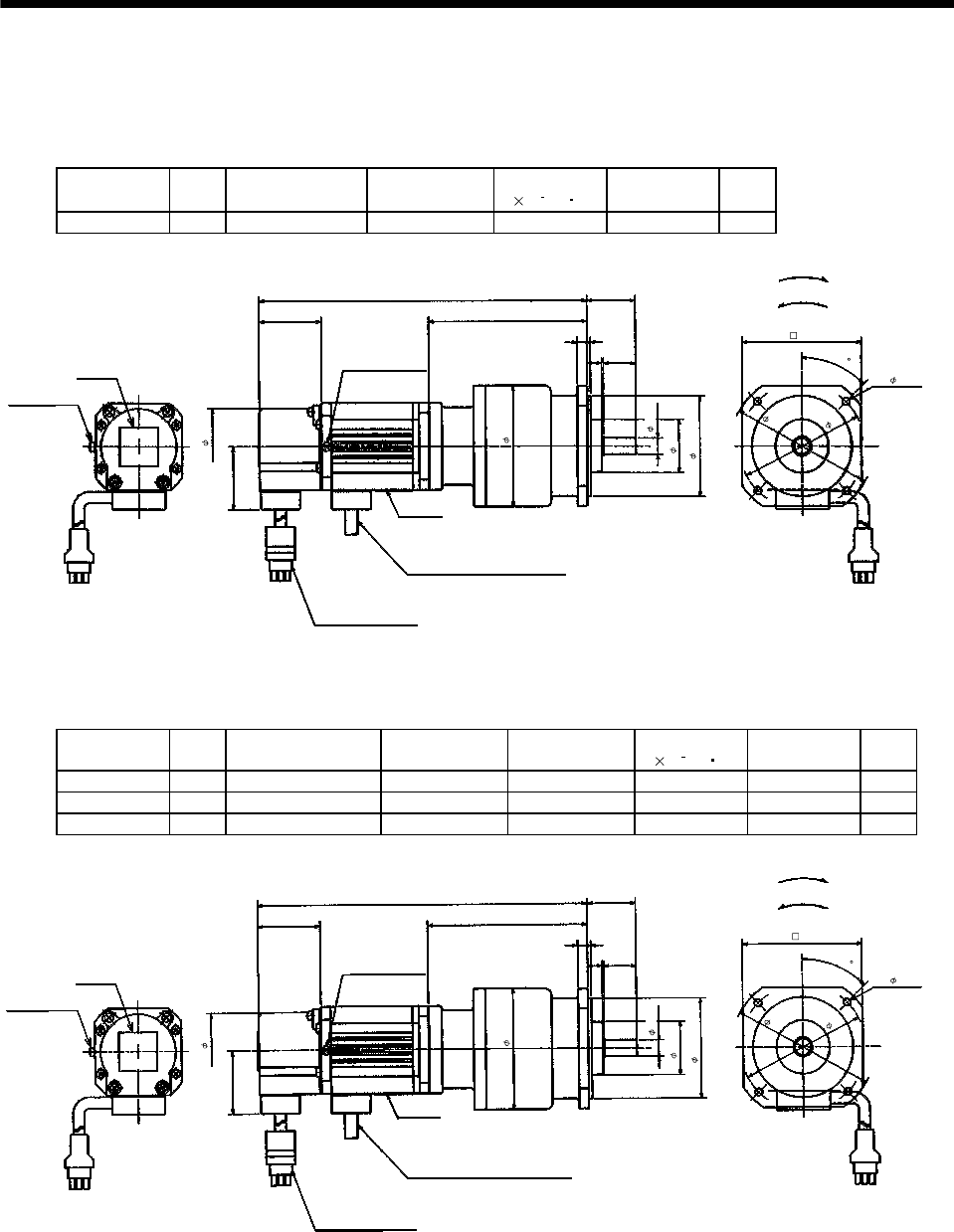
(4) With reduction gear for precision application
The outer frame of the reduction gear is a material surface such as casting. Its actual dimensions may
be 1 to 3mm larger than the drawing dimensions. Design the machine side with allowances.
(a) Without electromagnetic brake
Model
Output
[W]
Reduction Gear
Model
Reduction Ratio
Inertia Moment
J[
10
4
kg m
2
]
Backlash
Mass
[kg]
HA-FF053G2 50 BM2-05B-A5MES 1/5 0.11 3 min. max. 2.3
Motor plate
39
6
99
4- 4.5
30
Bottom
Top
39
Caution Plate
205
Earth terminal
M3 screw
(Opposite side)
47
Earth terminal M3
2
9
20
7
8
75
(Note)[Unit: mm]
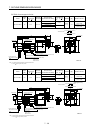
"Rotation direction"
For forward rotation command
For reverse rotation command
Power supply cable
VCTF 3-1.25 0.5m
(With end-insulated round crimping terminal 1.25-4)
2
Red: Phase U
White: Phase V
Black: Phase W
Encoder cable 0.3m
With connector 172169-9
(AMP)
Bottom
Top
10h6
74
Z694850*
33
62h7
8
9
4
5
Note: The dimensions without tolerances are reference dimensions.
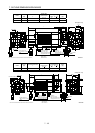
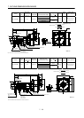
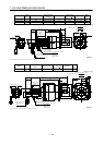
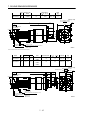
Model
Output
[W]
Variable dimensions L
Reduction Gear
Model
Reduction Ratio
Inertia Moment
J[
10
4
kg m
2
]
Backlash
Mass
[kg]
HA-FF053G2 50 205 BM2-10B-A5MES 1/10 0.108 3 min. max. 2.3
HA-FF053G2 50 205 BM2-15B-A5MES 1/15 0.105 3 min. max. 2.3
HA-FF13G2 100 205 BM2-05B-01MES 1/5 0.143 3 min. max. 2.5
Motor plate
39
6
99
74
4- 4.5
Z694805*
62h7
30
BottomTop
39
Caution plate
L
Earth terminal
M3 screw
(Opposite side)
47
Earth terminal M3
2
9
20
33
7
8
8
9
75
(Note)[Unit: mm]
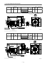
"Rotation direction"
For forward rotation command
For reverse rotation command
Power supply cable
VCTF 3-1.25 0.5m
(With end-insulated round crimping terminal 1.25-4)
2
Red: Phase U
White: Phase V
Black: Phase W
Encoder cable 0.3m
With connector 172169-9
(AMP)
Top
Bottom
10h6
4
5
Note: The dimensions without tolerances are reference dimensions.