


7 - 83
7. OUTLINE DIMENSION DRAWINGS
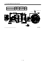
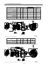
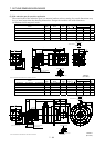
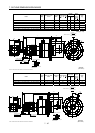
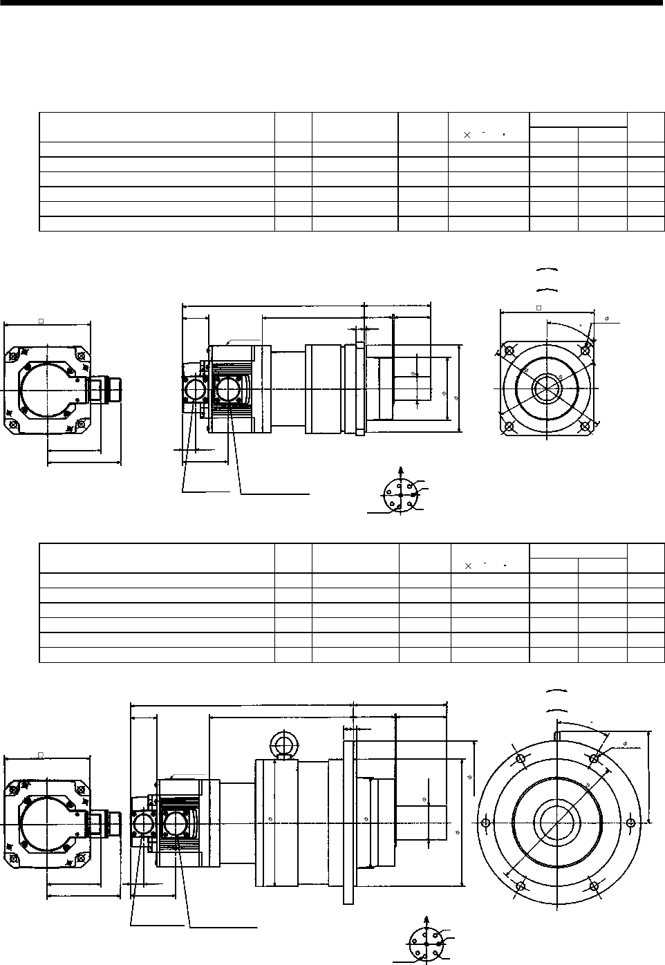
(5) With reduction gear for precision application
The outer frame of the reduction gear is a material surface such as casting. Its actual dimensions may
be 1 to 3mm larger than the drawing dimensions. Design the machine side with allowances.
(a) Without electromagnetic brake
Variable Dimensions
Model
Output
[kW]
Reduction Gear
Model
Reduction
Ratio
Inertia Moment
J[
10
4
kg m
2
]
LH
Mass
[kg]
HC-SF52G2 HC-SFS52G2 HC-SFS524G2 0.5 BL2-05B-05MEH 1/5 7.9 276 156 13
HC-SF52G2 HC-SFS52G2 HC-SFS524G2 0.5 BL2-09B-05MEH 1/9 7.55 288 168 13
HC-SF52G2 HC-SFS52G2 HC-SFS524G2 0.5 BL2-20B-05MEH 1/20 8.03 309 189 15
HC-SF102G2 HC-SFS102G2 HC-SFS1024G2 1.0 BL2-05B-10MEH 1/5 15.0 301 156 15
HC-SF102G2 HC-SFS102G2 HC-SFS1024G2 1.0 BL2-09B-10MEH 1/9 14.6 313 168 15
HC-SF152G2 HC-SFS152G2 HC-SFS1524G2 1.5 BL2-05B-15MEH 1/5 21.2 326 156 17
19.5
W
V
U
L
55
100
A
F
G
H
B
E
C
D
111
81.5
68.5
39.5
H
43
12
3
94
MS3102A20-29P
CE05-2A22-23P
Bottom Top
Encoder connector
Power supply connector
Motor flange direction
Earth
Power supply connector layout
CE05-2A22-23P
(Note)[Unit: mm]
Motor plate
[Side view of motor only]
"Rotation direction"
For reverse
rotation command
For forward
rotation command
4
5
130
4- 12
1
8
5
1
6
0
140
130h7
35h6
Z695320*
(BC11849*)
Note: The dimensions without tolerances are reference dimensions.
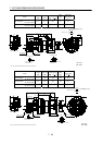
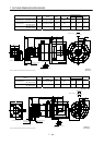
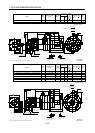
Variable Dimensions
Model
Output
[kW]
Reduction Gear
Model
Reduction
Ratio
Inertia Moment
J[
10
4
kg m
2
]
LH
Mass
[kg]
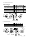
HC-SF52G2 HC-SFS52G2 HC-SFS524G2 0.5 BL3-29B-05MEH 1/29 9.4 337 217 30
HC-SF52G2 HC-SFS52G2 HC-SFS524G2 0.5 BL3-45B-05MEH 1/45 8.43 343 223 30
HC-SF102G2 HC-SFS102G2 HC-SFS1024G2 1.0 BL3-20B-10MEH 1/20 18.4 362 217 32
HC-SF102G2 HC-SFS102G2 HC-SFS1024G2 1.0 BL3-29B-10MEH 1/29 16.5 362 217 32
HC-SF152G2 HC-SFS152G2 HC-SFS1524G2 1.5 BL3-09B-15MEH 1/9 24.7 379 209 34
HC-SF152G2 HC-SFS152G2 HC-SFS1524G2 1.5 BL3-20B-15MEH 1/20 24.6 387 217 34
19.5
W
V
U
L
75
140
A
F
G
H
B
E
C
D
111
81.5
68.5
39.5
H
63
15
5
137
3
0
MS3102A20-29P
CE05-2A22-23P
Bottom
Top
Encoder connector
Power supply connector
Motor flange direction
Earth
Power supply connector layout
CE05-2A22-23P
(Note)[Unit: mm]
Motor plate
[Side view of motor only]
"Rotation direction"
For reverse
rotation command
For forward
rotation command
Z695321A
(BC11850*)
190h7
50h6
245
135
190
130
6- 12
220
Note: The dimensions without tolerances are reference dimensions.