


6 - 4
6. CHARACTERISTICS
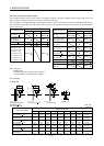
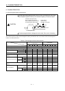
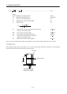
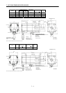
(2) Electromagnetic brake power supply
24VDC of the internal power output for interface (VDD) cannot be used. Prepare the following power
supply for use with the electromagnetic brake only.
VAR
B1
B2
24VDC powe
r
supply for
electromagnetic brake
or
B1
B2
VAR
24VDC power
supply for
electromagnetic brake
Electromagnetic
Electromagnetic
RA RA
The surge absorber (VAR) must be installed across B1-B2. For the selection of the surge absorber,
refer to OPTIONS AND AUXILIARY EQUIPMENT of the Servo Amplifier Instruction Manual.
The electromagnetic brake terminals (B1, B2) have no polarity.
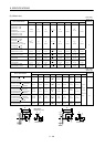
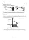
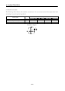
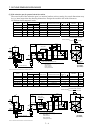
(3) Coasting distance
At an emergency stop, the servo motor will decelerate to a stop in the pattern shown in the following
diagram. Here, the maximum coasting distance (during fast feed), Lmax, will be the area shown with
the diagonal line in the figure and can be calculated approximately with Equation 6.1. The effect of the
load torque is greater near the stopping area. When the load torque is large, the servo motor will stop
faster than the value obtained in the equation.
Emergency stop
Brake current
Machine speed
V
0
t
1
t
2
t
3
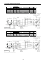
(4) Others
A leakage magnetic flux will occur at the shaft end of the servo motor equipped with electromagnetic
brake. Note that chips, screws and other magnetic substances are attracted.