


8 - 9
8. CALCULATION METHODS FOR DESIGNING
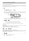
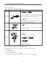
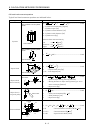
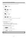
8.8 Load inertia moment equations
Typical load inertia moment equations are indicated below:
Type Mechanism Equation
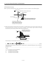
Axis of rotation is on the cylinder
center
Axis of rotation
L
D
1
D
2
JL0 =
32
L
(D D )
4
1
4
2
8
W
(D D )
2
1
2
2
..........................(8.22)
: Cylinder material density [kg/cm
3
]
L : Cylinder length [cm]
D
1 : Cylinder outside diameter [cm]
D2 : Cylinder inside diameter [cm]
W : Cylinder mass [kg]
Reference data: material density
Iron : 7.8
10
3
[kg/cm
3
]
Aluminum : 2.7
10
3
[kg/cm
3
]
Copper : 8.96 10
3
[kg/cm
3
]
Cylinder
A
xis of rotation is off the cylinder
Axis of rotation
D
R
cente
r
JL0
8
W
(D 8R )
22
...............................................................(8.23)
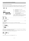
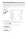
Square block
A
xis of rotation
R
a
a
b
b
JL0 W
3
a
2
b
2
R
2
..........................................................(8.24)
W : Square block mass [kg]
a, b, R : Left diagram [cm]
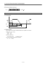
Object which
moves linearly
Servo motor
V
W
N
JL W
600
V
2
1
W
N 10
V
2
W
20
2
S
..............(8.25)
V : Speed of object moving linearly [mm/min]
S : Moving distance of object moving linearly per servo
motor revolution [mm/rev]
W : Object mass [kg]
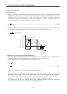
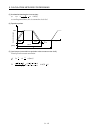
Object that is
hung with pulley
Servo motor
W
D
JL W
2
D
2
Jp
..................................................................(8.26)
J
P : Pulley inertia moment [kg cm
2
]
D : Pulley diameter [cm]
W : Object mass [kg]
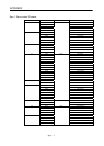
Converted load
Load A
J
A
J
31
N
3
J
21
J
11
J
22
N
2
N
1
Load B
J
B
JL J11 (J21 J22 JA)
N1
N
2
2
(J
31
J
B
)
N1
N
3
2
..................(8.27)
J
A, JB : Inertia moments of loads A, B [kg cm
2
]
J
11 to J31 : Inertia moments [kg cm
2
]
N
1 to N3 : Speed of each shaft [r/min]