


7 - 96
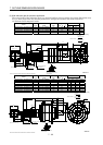
7. OUTLINE DIMENSION DRAWINGS
Model
Output
[kW]
Reduction Gear
Model
Reduction
Ratio
Brake static
friction torque
[N
m]
Inertia Moment
J[
10
4
kg m
2
]
Mass
[kg]
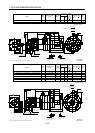
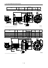
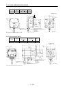
HC-RF353BG2 HC-RFS353BG2 3.5 BL3-05B-35MEKD 1/5 16.7 20.8 33
Earth
W
V
U
Power supply connector layout
CE05-2A24-10P
Motor flange direction
A
F
G
B
E
C
D
Encoder connector
MS3102A20-29P
Power supply connector
CE05-2A24-10P
Bottom
Top
455
39.5
63
140
75
81.5
120
(Side view of motor only)
15
5
201
Motor plate
19.5
106
For reverse
rotation command
For forward
rotation command
"Rotation direction"
136.5
3
0
74
Brake
(Note)[Unit: mm]
130
6- 12
2
2
0
135
190
190h7
50h6
245
Z695991A
(********)
Note: The dimensions without tolerances are reference dimensions.
Variable
Dimensions
Model
Output
[kW]
Reduction Gear
Model
Reduction
Ratio
LHLI
Brake static
friction torque
[N
m]
Inertia Moment
J[
10
4
kg m
2
]
Mass
[kg]
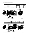
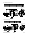
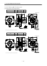
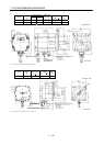
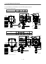
HC-RF353BG2 HC-RFS353BG2 3.5 BL4-09B-35MEKD 1/9 507 253 126 16.7 23.1 60
HC-RF353BG2 HC-RFS353BG2 3.5 BL4-20B-35MEKD 1/20 507 253 126 16.7 30.8 60
HC-RF353BG2 HC-RFS353BG2 3.5 BL4-29B-35MEKD 1/29 507 253 126 16.7 22.0 60
HC-RF503BG2 HC-RFS503BG2 5.0 BL4-05B-50MEKD 1/5 532 221 94 16.7 34.4 56
HC-RF503BG2 HC-RFS503BG2 5.0 BL4-09B-50MEKD 1/9 564 253 126 16.7 26.5 66
HC-RF503BG2 HC-RFS503BG2 5.0 BL4-20B-50MEKD 1/20 564 253 126 16.7 34.2 66
Earth
W
V
U
Motor flange direction
A
F
G
B
E
C
D
Encoder connector
MS3102A20-29P
Power supply connector
CE05-2A24-10P
Bottom
Top
L
39.5
68
160
90
81.5
120
18
5
H
Motor plate
19.5
106
171
3
0
LI
Brake
(Note)[Unit: mm]
For forward
rotation command
For reverse
rotation command
"Rotation direction"
(Side view of motor only)
Power supply connector layout
CE05-2A24-10P
60h6
240h7
186
240
310
2
8
0
6- 14
(********)
130
Z695993A
Note: The dimensions without tolerances are reference dimensions.