


7 - 4
7. OUTLINE DIMENSION DRAWINGS
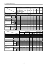
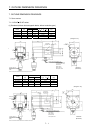
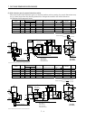
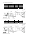
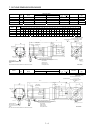
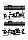
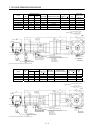
(3) With reduction gear for general industrial machine
The outer frame of the reduction gear is a material surface such as casting. Its actual dimensions may
be 1 to 3mm larger than the drawing dimensions. Design the machine side with allowances.
(a) Without electromagnetic brake
Variable Dimensions
Model
Output
[W]
LKL
Reduction
Gear Model
Reduction Ratio
(Actual Reduction Ratio)
Inertia Moment
J[
10
4
kg m
2
]
Backlash
Mass
[kg]
HC-MF053G1 50 126 74 K6505 1/5(9/44) 0.055 60min. max. 1.4
HC-MF053G1 50 144 92 K6512 1/12(49/576) 0.077 60min. max. 1.8
HC-MF053G1 50 144 92 K6520 1/20(25/484) 0.059 60min. max. 1.8
HC-KF053G1 50 126 74 K6505 1/5(9/44) 0.090 60min. max. 1.4
HC-KF053G1 50 144 92 K6512 1/12(49/576) 0.112 60min. max. 1.8
HC-KF053G1 50 144 92 K6520 1/20(25/484) 0.094 60min. max. 1.8
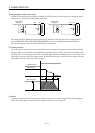
BC12066A
(BC12086A)
L
60.5
25
34.5
6.58
40.5
9.9
28.7
25.2
35.7
20
6.8
(
R
4
)
Motor
plate
Caution
plate
Encoder cable 0.3m
With connector 1-172169-9 (AMP)
Power supply lead 4-AWG19 0.3m
(Opposite side)
(With end-insulated round crimping terminal 1.25-4)
Red: Phase U
White: Phase V
Black: Phase W
Green/yellow: Earth
"Rotation direction"
For forward rotation command
For reverse rotation command
M4 threads,
depth 8
16h6
48
( 50)
60h7
75
8
8
4- 7
65
Motor plate
Top
Bottom
Top
Bottom
4
5
42
KL
(Note)[Unit: mm]
Note: The dimensions without tolerances are reference dimensions.
Bottom
Top
Variable Dimensions
Model
Output
[W]
LKL
Reduction
Gear Model
Reduction Ratio
(Actual Reduction Ratio)
Inertia Moment
J[
10
4
kg m
2
]
Backlash
Mass
[kg]
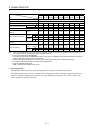
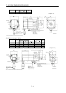
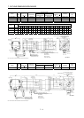
HC-MF13G1 100 141 89 K6505 1/5(9/44) 0.067 60min. max. 1.5
HC-MF13G1 100 159 107 K6512 1/12(49/576) 0.089 60min. max. 1.9
HC-MF13G1 100 159 107 K6520 1/20(25/484) 0.071 60min. max. 1.9
HC-KF13G1 100 141 89 K6505 1/5(9/44) 0.121 60min. max. 1.5
HC-KF13G1 100 159 107 K6512 1/12(49/576) 0.143 60min. max. 1.9
HC-KF13G1 100 159 107 K6520 1/20(25/484) 0.125 60min. max. 1.9
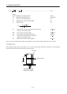
BC12067A
(BC12087A)
28.7
25.2
25
34.5
40.5
6.8
8
6.5
9.9
KL
35.7
20
60.5
L
(
R
4
)
Motor
plate
Caution
plate
Top
Bottom
Encoder cable 0.3m
With connector 1-172169-9 (AMP)
Power supply lead 4-AWG19 0.3m
(With end-insulated round crimping terminal 1.25-4)
Red: Phase U
White: Phase V
Black: Phase W
Green/yellow: Earth
Motor plate
(Opposite side)
Top
Bottom
"Rotation direction"
For forward rotation command
For reverse rotation command
M4 threads,
depth 8
16h6
48
( 50)
60h7
7
5
8
8
4- 7
65
4
5
42
(Note)[Unit: mm]
Note: The dimensions without tolerances are reference dimensions.
Bottom
Top