


7 - 219
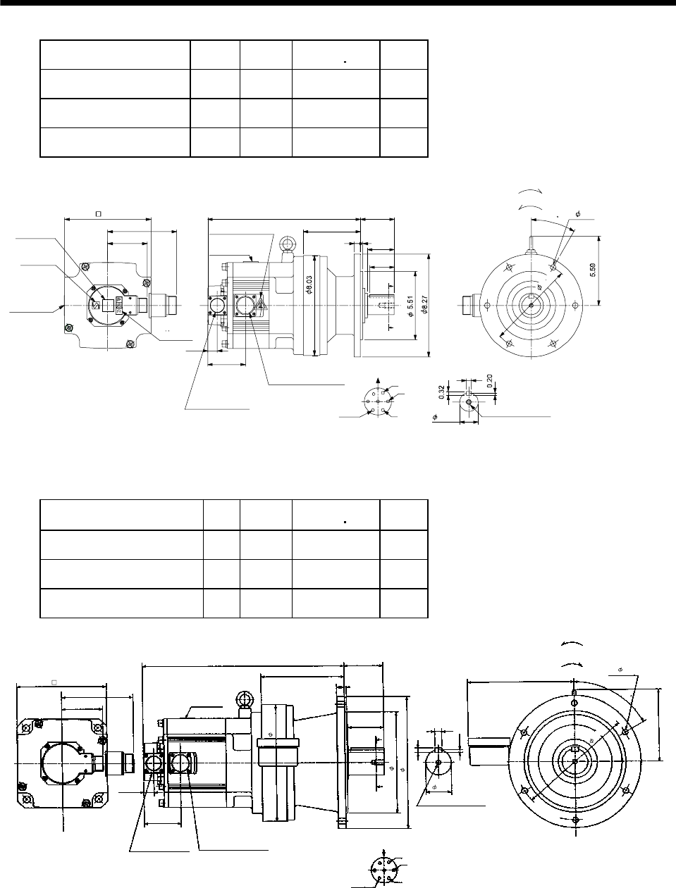
7. OUTLINE DIMENSION DRAWINGS
Model
Output
[kW]
Reduction
Ratio
Inertia Moment
WK
2
[oz in
2
]
Mass
[lb]
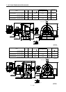
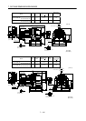
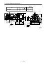
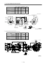
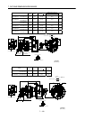
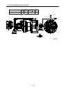
HC-SF202G1
HC-SFS202G1
HC-SFS2024G1
2.0 1/6 249.32 75.0
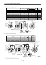
HC-SF202G1
HC-SFS202G1
HC-SFS2024G1
2.0 1/11 241.11 75.0
HC-SF202G1
HC-SFS202G1
HC-SFS2024G1
2.0 1/17 238.93 75.0
0.51
0.16
2.17
4.61
2.72
12.3
3.21
5.59
3.01
A
B
C
D
E
F
G
0.39
Z695806A
BC11814B BC30689*
A
A
1.97
0.77
Encoder connector
Power supply connector
V
U
CE05-2A24-10P
MS3102A20-29P
W
Motor plate
Caution plate
Caution plate (Note 2)
(Opposite side)
1.50
6.93
Caution plate
Logo plate
(Note 2)
Side view of motor only
6- 0.43
Section AA
Power supply connector layout
Top
Bottom
TopBottom
Top
Bottom
Top
Bottom
For forward rotation command
"Rotation direction"
For reverse rotation command
Earth
CE05-2A24-10P
M8 screw, depth 0.79
Motor flange direction
TUV plate
3
0
7
.
0
9
(Note 1)[Unit: in]
Note 1. The dimensions without tolerances are reference dimensions.
2. This caution plate is attached to the 400V class motors only, not to the 200V class.
Model
Output
[kW]
Reduction
Ratio
Inertia Moment
WK
2
[oz in
2
]
Mass
[lb]
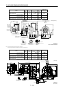
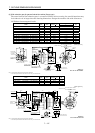
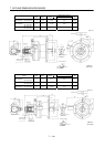
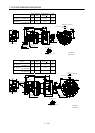
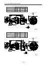
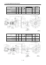
HC-SF352G1
HC-SFS352G1
HC-SFS3524G1
3.5 1/6 492.62 125.7
HC-SF352G1
HC-SFS352G1
HC-SFS3524G1
3.5 1/11 471.29 125.7
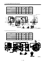
HC-SF352G1
HC-SFS352G1
HC-SFS3524G1
3.5 1/17 464.73 125.7
5.59
15.63
2.99
2.76
6.93
3.21
A
A
3.01
5.59
0.22
Z695807A
1.97
0.35
8.23
U
V
W
CD
B
E
A
G
F
6.46
9.06
7.87
10.24
0.16
0.59
0.77
6- 0.43
0.55
MS3102A20-29P
CE05-2A24-10P
Bottom Top
Encoder connector
Power supply connector
Motor flange direction
Earth
Power supply connector layout
CE05-2A24-10P
[Unit: in]
Motor plate
[Side view of motor only]
"Rotation direction"
For reverse
rotation command
For forward
rotation command
Section A-A
M10 threads, depth 0.71
9
.
0
6
(BC11816*)
6
0