


7 - 209
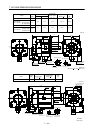
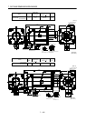
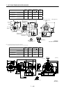
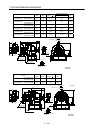
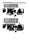
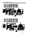
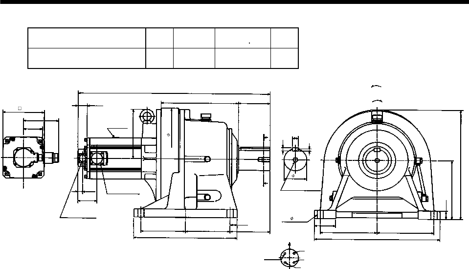
7. OUTLINE DIMENSION DRAWINGS
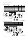
Model
Output
[kW]
Reduction
Ratio
Inertia Moment
WK
2
[oz in
2
]
Mass
[lb]
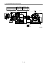
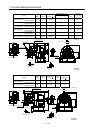
HC-SF702G1H
HC-SFS702G1H
HC-SFS7024G1H
7.0 1/43 1404.04 575
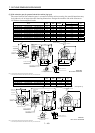
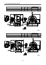
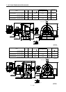
Power supply connector layout
CE05-2A32-17P
5.91
32.28
12.99
5.32
3.74
3.21
A
A
Motor plate
0.77
3.21
18.31
0.35
9.84
BC10755*
1.38
3.54
9.45
9.45
20.87
4- 1.62
0.55
Motor flange direction
0.98
U
V
W
C
D
B
A
Earth
Section A-A
6.69
1.18
7.48
7.48
17.32
16.93
Encoder connector
MS3102A20-29P
1.56
8.27
6.93
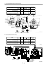
Bottom Top
[Side view of motor only]
[Unit: in]
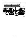
"Rotation direction"
For reverse
rotation command
For forward
rotation command
M20 threads,
depth 1.34
Power supply
connector
CE05-2A32-17P
(BC11809*)