


7 - 264
7. OUTLINE DIMENSION DRAWINGS
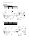
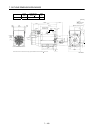
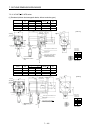
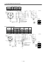
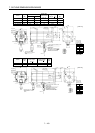
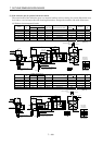
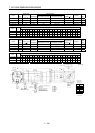
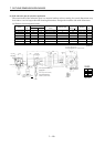
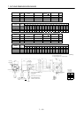
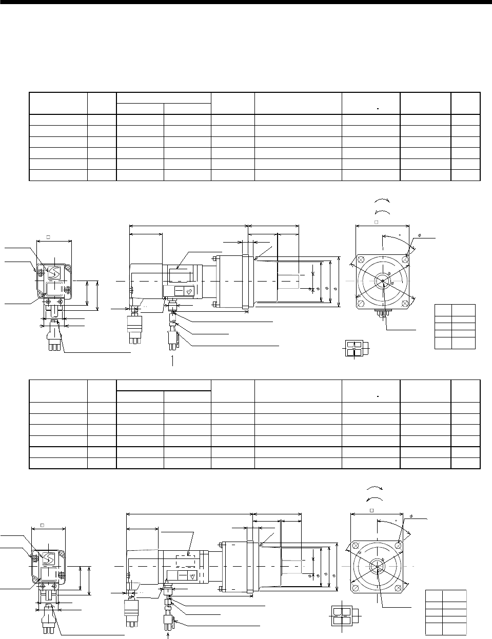
(3) With reduction gear for general industrial machine
The outer frame of the reduction gear is a material surface such as casting. Its actual dimensions may
be 0.039 to 0.118 in larger than the drawing dimensions. Design the machine side with allowances.
(a) Without electromagnetic brake
Variable Dimensions [in]
Model
Output
[W]
LKL
Reduction
Gear Model
Reduction Ratio
(Actual Reduction Ratio)
Inertia Moment
WK
2
[oz in
2
]
Backlash
Mass
[lb]
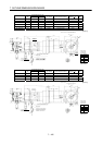
HC-MFS053G1 50 4.96 2.91 K6505 1/5(9/44) 0.30 60min. max. 3.1
HC-MFS053G1 50 5.669 3.62 K6512 1/12(49/576) 0.42 60min. max. 4.0
HC-MFS053G1 50 5.669 3.62 K6520 1/20(25/484) 0.32 60min. max. 4.0
HC-KFS053G1 50 4.96 2.91 K6505 1/5(9/44) 0.49 60min. max. 3.1
HC-KFS053G1 50 5.669 3.62 K6512 1/12(49/576) 0.61 60min. max. 4.0
HC-KFS053G1 50 5.669 3.62 K6520 1/20(25/484) 0.51 60min. max. 4.0
TUV
Rheinland
CE
4
3
1
2
Bottom
[Unit: in]
With connector 1-172169-9
(AMP)
Protective tube
Motor plate
(Opposite side)
2
.
9
5
3
2.559
0.630
Logo plate
5557-04R-210 (Receptacle)
5556PBT (Female terminal)
Power supply connector (Molex)
Encoder cable 11.8in
Motor plate
Caution plate
Bottom
Top
KL
2.382
0.256
0.315
L
1.594
0.268
0.992
1.654
1.130
4- 0.276
Power supply lead 4-AWG19 11.8in
TUV plate
Arrow A
Top
Top
1.358
0.984
1.890
3
.
4
6
5
For reverse rotation command
For forward rotation command
"Rotation direction"
M4 threads,
depth 0.315
Arrow A
4
5
Bottom
Power supply
connector pin
connection list
1
2
3
4
Pin No.
Application
Phase U
Phase V
Phase W
Earth
BC11896A
(BC11924A)
1.406
2.362
0.787
APPROVED
TYPE
GEPRUFT
BAUART
Bottom
Top
0.390
(
R
4
)
Top
Bottom
( 1.969)
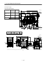
Variable Dimensions [in]
Model
Output
[W]
LKL
Reduction
Gear Model
Reduction Ratio
(Actual Reduction Ratio)
Inertia Moment
WK
2
[oz in
2
]
Backlash
Mass
[lb]
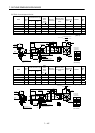
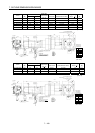
HC-MFS13G1 100 5.551 3.5 K6505 1/5(9/44) 0.36 60min. max. 3.31
HC-MFS13G1 100 6.26 4.21 K6512 1/12(49/576) 0.48 60min. max. 4.19
HC-MFS13G1 100 6.26 4.21 K6520 1/20(25/484) 0.38 60min. max. 4.19
HC-KFS13G1 100 5.551 3.5 K6505 1/5(9/44) 0.66 60min. max. 3.31
HC-KFS13G1 100 6.26 4.21 K6512 1/12(49/576) 0.78 60min. max. 4.19
HC-KFS13G1 100 6.26 4.21 K6520 1/20(25/484) 0.68 60min. max. 4.19
TUV Rheinland
CE
42
13
Bottom
[Unit: in]
With connector 1-172169-9
(AMP)
Protective tube
Motor plate
(Opposite side)
2
.
9
5
3
2.559
0.630
Logo plate
5557-04R-210 (Receptacle)
5556PBT (Female terminal)
Power supply connector (Molex)
Encoder cable 11.8in
Motor plate
Caution plate
Bottom
Top
KL
2.382
(
R
4
)
0.315
L
1.594
0.787
0.992
1.654
1.130
4- 0.276
Power supply lead 4-AWG19 11.8in
TUV plate
Arrow A
Top
Top
1.358 0.984
1.890
3
.
4
6
5
For reverse rotation command
For forward rotation command
"Rotation direction"
M4 threads,
depth 0.315
Arrow A
4
5
Bottom
Power supply
connector pin
connection list
1
2
3
4
Pin No.
Application
Phase U
Phase V
Phase W
Earth
BC11925A
(BC11897A)
1.406
2.362
0.256
APPROVED
TYPE
GEPRUFT
BAUART
Bottom
Top
Top
Bottom
0.268
0.390
( 1.969)