


7 - 72
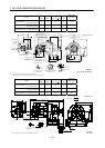
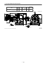
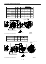
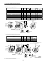
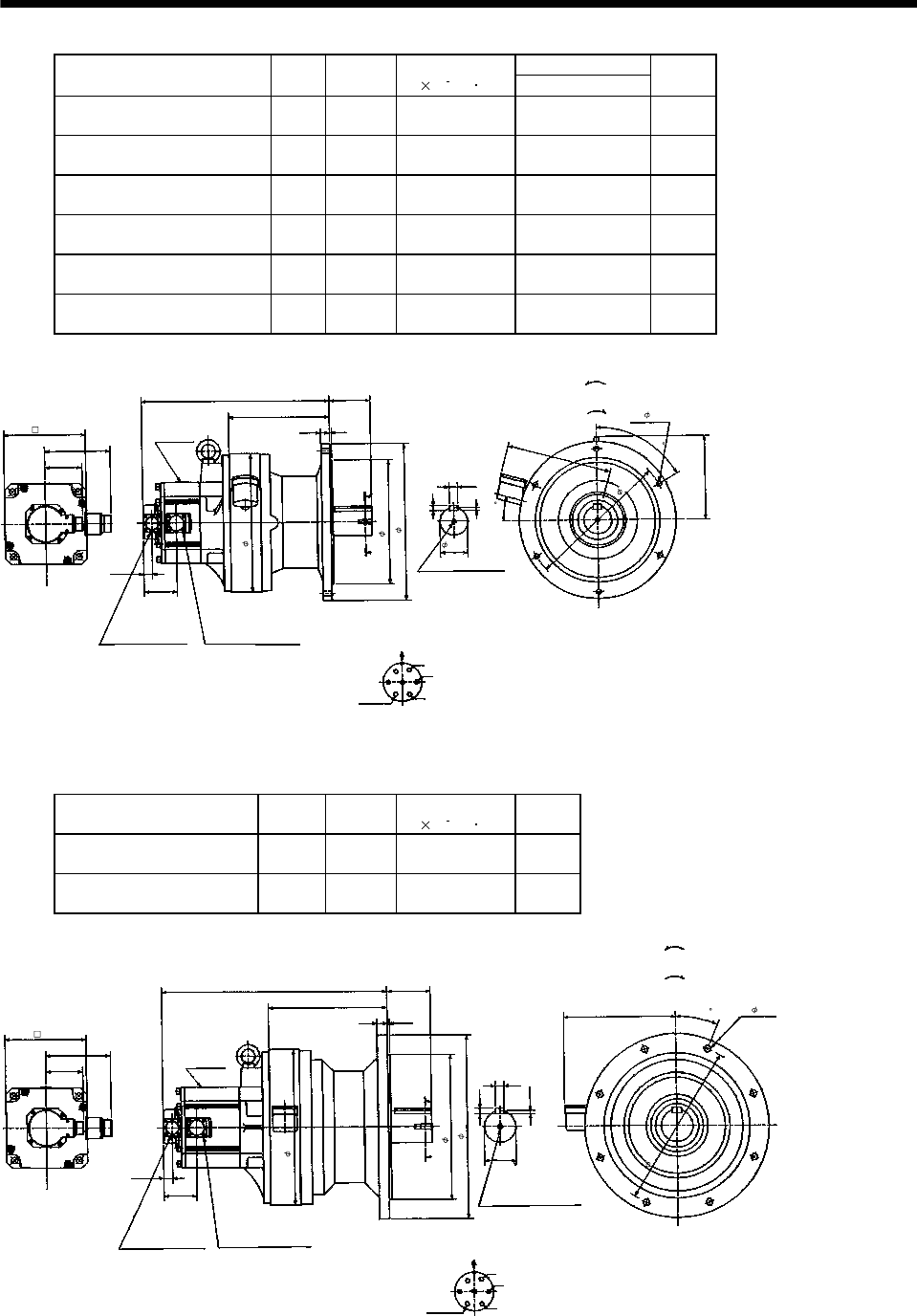
7. OUTLINE DIMENSION DRAWINGS
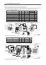
Variable Dimensions
Model
Output
[kW]
Reduction
Ratio
Inertia Moment
J[
10
4
kg m
2
]
L
Mass
[kg]
HC-SF202G1
HC-SFS202G1
HC-SFS2024G1
2.0 1/29 48.9 409 84
HC-SF202G1
HC-SFS202G1
HC-SFS2024G1
2.0 1/35 48.6 409 84
HC-SF202G1
HC-SFS202G1
HC-SFS2024G1
2.0 1/43 48.4 409 84
HC-SF202G1
HC-SFS202G1
HC-SFS2024G1
2.0 1/59 48.3 409 84
HC-SF352G1
HC-SFS352G1
HC-SFS3524G1
3.5 1/29 88.4 451 91
HC-SF352G1
HC-SFS352G1
HC-SFS3524G1
3.5 1/35 88.1 451 91
142
L
89
4
81.5
A
A
76.5
181
7
6
0
11
18
U
V
W
CD
B
E
A
G
F
219
4
20
19. 5
2
2
8
1
5
Section A-A
M10 threads, depth 18
MS3102A20-29P
CE05-2A24-10P
Bottom
Top
Encoder connector
Power supply connector
Motor flange direction
Earth
Power supply connector layout
CE05-2A24-10P
(Note)[Unit: mm]
Motor plate
[Side view of motor only]
"Rotation direction"
For reverse
rotation command
For forward
rotation command
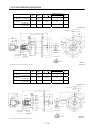
3
1
0
6- 11
60h6
270f8
340
300
176
Z695808A
(BC11815*)
Note: The dimensions without tolerances are reference dimensions.
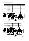
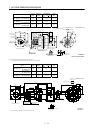
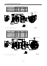
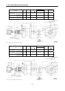
Model
Output
[kW]
Reduction
Ratio
Inertia Moment
J[
10
4
kg m
2
]
Mass
[kg]
HC-SF352G1
HC-SFS352G1
HC-SFS3524G1
3.5 1/43 106.5 133
HC-SF352G1
HC-SFS352G1
HC-SFS3524G1
3.5 1/59 105.9 133
142
94
81.5
A
A
76.5
12
2
2
.
5
7.5
20
U
V
W
CDBE
A
G
F
70h6
490
5
22
19. 5
243
258
MS3102A20-29P
CE05-2A24-10P
Bottom Top
Encoder connector
Power supply connector
Motor flange direction
Earth
Power supply connector layout
CE05-2A24-10P
(Note)[Unit: mm]
Motor plate
[Side view of motor only]
"Rotation direction"
For reverse
rotation command
For forward
rotation command
1-M12 threads, depth 24
Section A-A
176
8- 14
3
6
0
316f8
400
340
Z695809A
(BC11817*)
Note: The dimensions without tolerances are reference dimensions.