


7 - 127
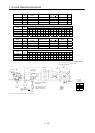
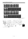
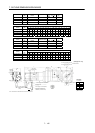
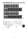
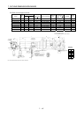
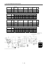
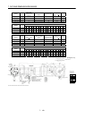
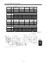
7. OUTLINE DIMENSION DRAWINGS
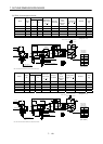
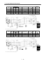
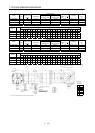
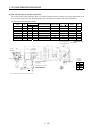
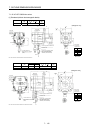
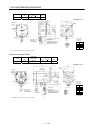
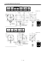
(b) With electromagnetic brake
Variable Dimensions
Model
Output
[W]
LKL
Brake static
friction torque
[N
m]
Reduction Gear Model
Reduction
Ratio
Inertia Moment
J[
10
4
kg m
2
]
Backlash
Mass
[kg]
HC-MFS053BG2 50 158 78 0.32 BK1-05B-A5MEKA 1/5 0.070 3 min. max. 1.8
HC-MFS053BG2 50 174 94 0.32 BK1-09B-A5MEKA 1/9 0.063 3 min. max. 2.1
HC-MFS053BG2 50 174 94 0.32 BK1-20B-A5MEKA 1/20 0.072 3 min. max. 2.2
HC-MFS053BG2 50 174 94 0.32 BK1-29B-A5MEKA 1/29 0.060 3 min. max. 2.2
HC-KFS053BG2 50 158 78 0.32 BK1-05B-A5MEKA 1/5 0.104 3 min. max. 1.8
HC-KFS053BG2 50 174 94 0.32 BK1-09B-A5MEKA 1/9 0.098 3 min. max. 2.1
HC-KFS053BG2 50 174 94 0.32 BK1-20B-A5MEKA 1/20 0.107 3 min. max. 2.2
HC-KFS053BG2 50 174 94 0.32 BK1-29B-A5MEKA 1/29 0.095 3 min. max. 2.2
(Note)[Unit: mm]
Logo plate
Motor plate
With connector 1-172169-9
(AMP)
Encoder cable 0.3m
Motor plate
(Opposite side)
8
55
L
40.5
6
23 25
65.5
9.9
KL
25.2
Top
28.7
Bottom
Top
TUV plate
Caution plate
42
For reverse rotation command
For forward rotation command
Rotation direction
70
8
0
M4 threads, depth 8
16h6
48
55h7
20
14
2
5
4 - 6.6
Top
Bottom
5557-06R-210 (Receptacle)
5556PBTL (Female terminal)
Power supply connector (Molex)
Protective tube
Power supply lead 4-AWG19 0.3m
60
Arrow A
35.7
3
6
Arrow A
BC11911*
(BC11920*)
Break lead
2-0.3 0.3m
2
Power supply
connector pin
connection list
1
2
3
4
Pin No.
Application
Phase U
Phase V
Phase W
Earth
5
6
B1
B2
6.8
Bottom
Top
4
5
Bottom
9
5
Note: The dimensions without tolerances are reference dimensions.
Banding band