


7 - 232
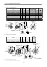
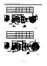
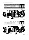
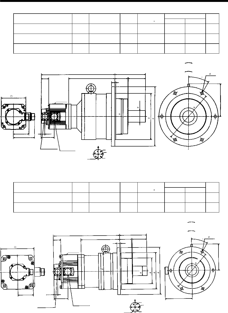
7. OUTLINE DIMENSION DRAWINGS
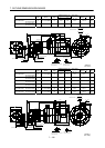
Variable Dimensions [in]
Model
Output
[kW]
Reduction Gear
Model
Reduction
Ratio
Inertia Moment
WK
2
[oz in
2
]
LH
Mass
[lb]
HC-SF102G2
HC-SFS102G2
HC-SFS1024G2
1.0 BL4-45B-10MEH 1/45 110.85 15.32 9.61 114.6
HC-SF152G2
HC-SFS152G2
HC-SFS1524G2
1.5 BL4-29B-15MEH 1/29 165.53 16.18 9.49 119.0
HC-SF152G2
HC-SFS152G2
HC-SFS1524G2
1.5 BL4-45B-15MEH 1/45 145.02 16.30 9.61 119.0
0.77
W
V
U
L
3.54
6.30
A
F
G
H
B
E
C
D
5.12
4.37
3.21
2.70
1.56
H
2.68
0.71
0.20
2.36
9.45
12.21
6- 0.55
7.32
6.73
1
1
.
0
2
Z695322*
Encoder
connector
MS3102A20-29P
Power supply connector
CE05-2A22-23P
Power supply connector layout
CE05-2A22-23P
Motor plate
Earth
Motor flange direction
[Unit: in]
Bottom Top
(Side view of motor only)
"Rotation direction"
For reverse
rotation command
For forward
rotation command
(BC11851*)
3
0
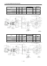
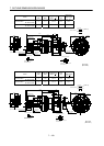
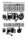
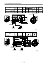
Variable Dimensions [in]
Model
Output
[kW]
Reduction Gear
Model
Reduction
Ratio
Inertia Moment
WK
2
[oz in
2
]
LH
Mass
[lb]
HC-SF202G2
HC-SFS202G2
HC-SFS2024G2
2.0 BL3-05B-20MEH 1/5 271.19 13.70 7.99 66.1
HC-SF202G2
HC-SFS202G2
HC-SFS2024G2
2.0 BL3-09B-20MEH 1/9 258.06 14.76 9.06 81.6
5.51
0.20
6.93
3.20
0.77
5.39
Z695637A
U
V
W
CDB
E
A
G
F
7.48
7.48
9.65
2.95
0.59
6- 0.47
3.01
5.32
2.48
L
H
1.56
5.59
Encoder connector
MS3102A20-29P
Power supply connector
CE05-2A24-10P
Power supply connector layout
CE05-2A24-10P
Motor plate
Motor flange direction
[Unit: in]
Bottom Top
(Side view of motor only)
"Rotation direction"
For reverse
rotation command
For forward
rotation command
Earth
1.97
8
.
6
6
(BC11852*)
3
0