


7 - 229
7. OUTLINE DIMENSION DRAWINGS
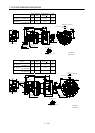
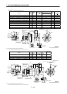
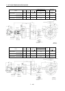
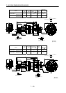
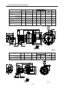
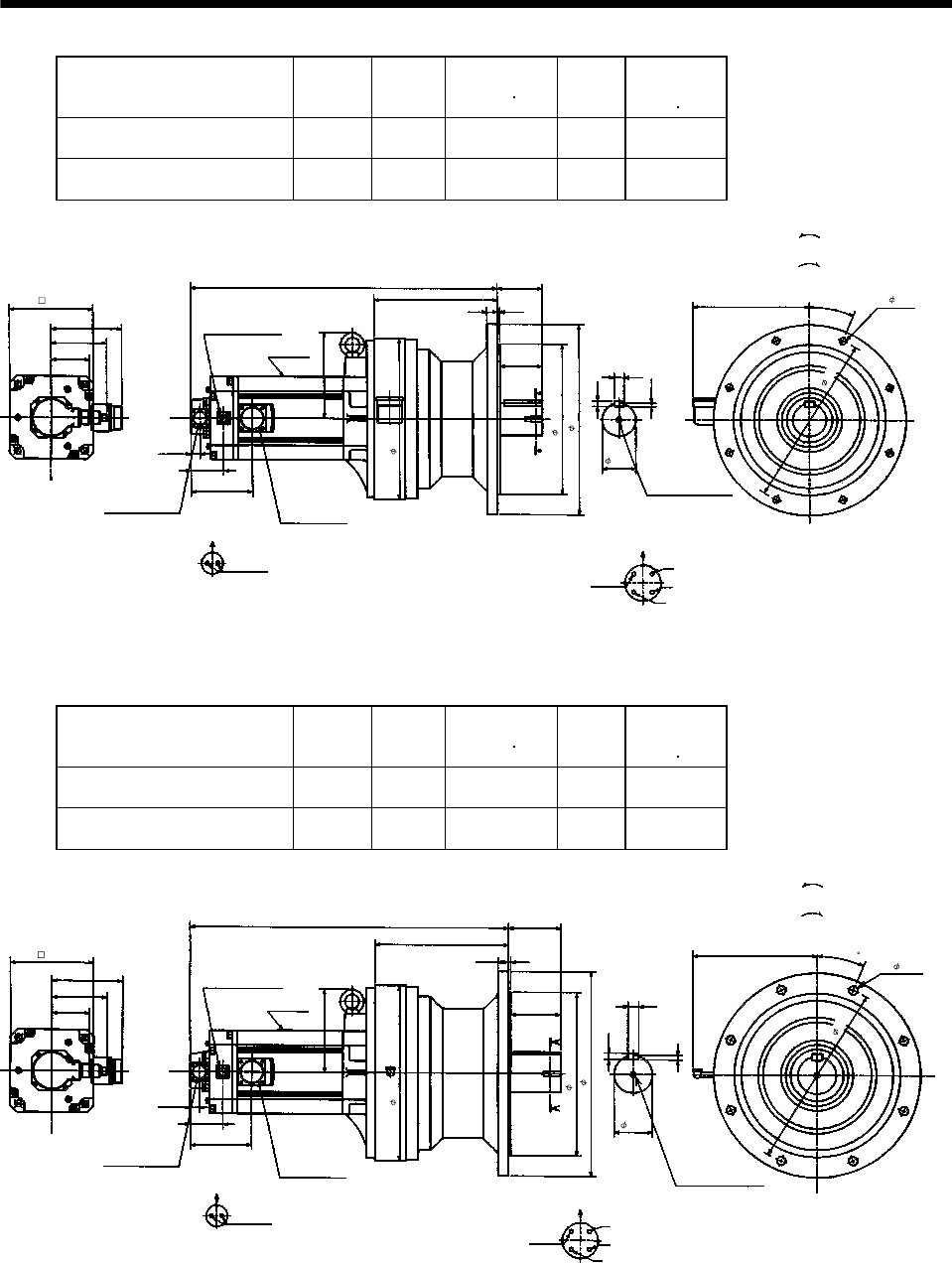
Model
Output
[kW]
Reduction
Ratio
Inertia Moment
WK
2
[oz in
2
]
Mass
[lb]
Brake static
friction torque
[oz
in]
HC-SF702BG1
HC-SFS702BG1
HC-SFS7024BG1
7.0 1/11 1141.60 335.1 6103
HC-SF702BG1
HC-SFS702BG1
HC-SFS7024BG1
7.0 1/17 1093.49 335.1 6103
5.91
25.32
10.16
3.70
2.76
4.61
A
A
0.77
2.72
0.30
BC11035*
8- 0.55
0.47
0.79
Motor flange direction
U
V
W
C
D
B
A
13.39
7.13
3.21
BA
5.10
0.87 0.20
3.50
12.44
15.75
9.57
1
4
.
1
7
Motor plate
Power supply connector layout
CE05-2A32-17P
Earth
Section A-A
Encoder connector
MS3102A20-29P
Power supply
connector
CE05-2A32-17P
Brake connector layout
MS3102A10SL-4P
Motor flange direction
Brake
Brake connector
MS3102A10SL-4P
6.93
Bottom Top
[Side view of motor only]
[Unit: in]
"Rotation direction"
For reverse
rotation command
For forward
rotation command
1-M12 threads,
depth 0.95
2
2
.
5
°
(BC11846*)
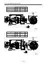
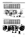
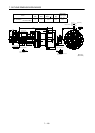
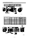
Model
Output
[kW]
Reduction
Ratio
Inertia Moment
WK
2
[oz in
2
]
Mass
[lb]
Brake static
friction torque
[oz
in]
HC-SF702BG1
HC-SFS702BG1
HC-SFS7024BG1
7.0 1/29 1134.50 390.2 6103
HC-SF702BG1
HC-SFS702BG1
HC-SFS7024BG1
7.0 1/35 1131.76 390.2 6103
26.26
10.98
4.33
3.15
4.61
A
A
Motor plate
0.77
2.72
0.35
BC11036*
8- 0.71
0.55
0.87
Power supply connector layout
CE05-2A32-17P
Motor flange direction
U
V
W
C
D
B
A
Earth
Section A-A
14.57
Encoder connector
MS3102A20-29P
Power supply
connector
CE05-2A32-17P
6.93
3.21
Brake connector layout
MS3102A10SL-4P
Motor flange direction
B
A
Brake
5.10
Brake connector
MS3102A10SL-4P
0.87
0.20
4.13
13.58
16.93
2
2
.
5
5.91
10.16
1
5
.
3
5
6.93
Bottom Top
[Side view of motor only]
[Unit: in]
"Rotation direction"
For reverse
rotation command
For forward
rotation command
1-M12 threads,
depth 0.95
(BC11847*)