


7 - 180
7. OUTLINE DIMENSION DRAWINGS
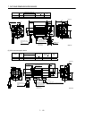
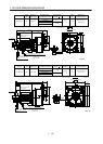
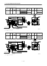
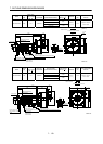
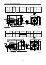
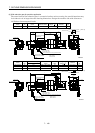
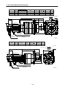
(4) With reduction gear for precision application
The outer frame of the reduction gear is a material surface such as casting. Its actual dimensions may
be 0.039 to 0.118 in larger than the drawing dimensions. Design the machine side with allowances.
(a) Without electromagnetic brake
Model
Output
[W]
Reduction Gear
Model
Reduction Ratio
Inertia Moment
WK
2
[oz in
2
]
Backlash
Mass
[lb]
HA-FF053G2 50 BM2-05B-A5MES 1/5 0.60 3 min. max. 5.1
Motor plate
1.54
0.24
3.898
Top
1.18
Bottom
Top
1.54
Caution Plate
8.07
Earth terminal M3 screw
(Opposite side)
Earth terminal M3
0.08
0.35
0.79
[Unit: in]
"Rotation direction"
For forward rotation command
For reverse rotation command
Power supply cable
VCTF 3-0.05 19.7in
(With end-insulated round crimping terminal 0.05-4)
2
Red: Phase U
White: Phase V
Black: Phase W
Encoder cable 11.8in
With connector 172169-9
(AMP)
1.85
1.30
2.44
2.95
3
.
5
0
3
.
0
7
4- 0.18
2.91
Z694850*
4
5
Bottom
0.39
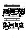
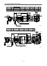
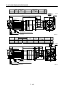
Variable Dimensions [in]
Model
Output
[W]
L
Reduction Gear
Model
Reduction
Ratio
Inertia Moment
WK
2
[oz in
2
]
Backlash
Mass
[lb]
HA-FF053G2 50 8.07 BM2-10B-A5MES 1/10 0.59 3 min. max. 5.1
HA-FF053G2 50 8.07 BM2-15B-A5MES 1/15 0.57 3 min. max. 5.1
HA-FF13G2 100 8.74 BM2-05B-01MES 1/5 0.78 3 min. max. 5.5
Motor plate
1.54
0.24
3.898
Top
1.18
BottomTop
1.54
Caution plate
L
Earth terminal M3 screw
(Opposite side)
Earth terminal M3
0.08
0.35
0.79
[Unit: in]
"Rotation direction"
For forward rotation command
For reverse rotation command
Power supply cable
VCTF 3-0.05 19.7in
(With end-insulated round crimping terminal 0.05-4)
2
Red: Phase U
White: Phase V
Black: Phase W
Encoder cable 11.8in
With connector 172169-9
(AMP)
Z694805*
2.91
4- 0.18
3
.
0
7
3
.
5
0
2.44
1.30
2.95
1.85
4
5
Bottom
0.39