


7 - 55
7. OUTLINE DIMENSION DRAWINGS
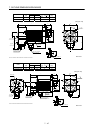
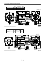
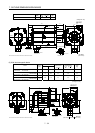
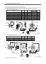
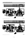
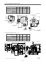
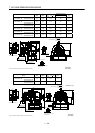
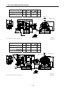
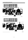
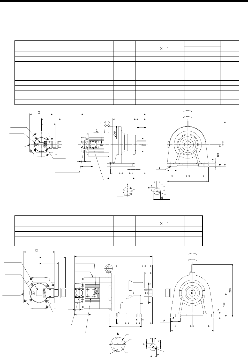
(3) With reduction gear for general industrial machine (leg type)
The outer frame of the reduction gear is a material surface such as casting. Its actual dimensions may
be 1 to 3mm larger than the drawing dimensions. Design the machine side with allowances.
(a) Without electromagnetic brake
Variable Dimensions
Model
Output
[kW]
Reduction
Ratio
Inertia Moment
J[
10
4
kg m
2
]
L
Mass
[kg]
HC-SF52G1H HC-SFS52G1H HC-SFS524G1H 0.5 1/35 7.5 338 28
HC-SF52G1H HC-SFS52G1H HC-SFS524G1H 0.5 1/43 7.45 338 28
HC-SF52G1H HC-SFS52G1H HC-SFS524G1H 0.5 1/59 7.43 338 28
HC-SF102G1H HC-SFS102G1H HC-SFS1024G1H 1.0 1/6 16.8 363 30
HC-SF102G1H HC-SFS102G1H HC-SFS1024G1H 1.0 1/11 15.3 363 30
HC-SF102G1H HC-SFS102G1H HC-SFS1024G1H 1.0 1/17 14.9 363 30
HC-SF102G1H HC-SFS102G1H HC-SFS1024G1H 1.0 1/29 14.6 363 30
HC-SF102G1H HC-SFS102G1H HC-SFS1024G1H 1.0 1/35 14.6 363 30
HC-SF152G1H HC-SFS152G1H HC-SFS1524G1H 1.5 1/6 23.1 388 32
HC-SF152G1H HC-SFS152G1H HC-SFS1524G1H 1.5 1/11 21.5 388 32
HC-SF152G1H HC-SFS152G1H HC-SFS1524G1H 1.5 1/17 21.2 388 32
81.5
111
A
B
C
D
E
F
G
H
Z695739A
BC11798A BC26016A
10
Encoder connector
V
U
CE05-2A22-23P
MS3102A20-29P
W
Caution plate
(Note 2)
Motor plate
(Opposite side)
4- 14
130
Caution plate
Caution plate
Logo plate
(Side view of motor only)
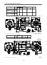
Section AA
Power supply connector layout
Top
Bottom
Top
Bottom
TopBottom
For forward rotation command
"Rotation direction"
For reverse rotation command
TopBottom
Earth
CE05-2A22-23P
M8 screw, depth 20
Motor flange direction
TUV plate
(Note 2)
38h6
Power supply connector
(Note 1)[Unit: mm]
9595
230
55
131
L
8257.5 57.5
155
20
19.5
68.5
A
A
55
50
Note 1. The dimensions without tolerances are reference dimensions.
2. This caution plate is attached to the 400V class motors only, not to the 200V class.
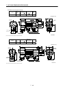
Model
Output
[kW]
Reduction
Ratio
Inertia Moment
J[
10
4
kg m
2
]
Mass
[kg]
HC-SF52G1H HC-SFS52G1H HC-SFS524G1H 0.5 1/6 7.33 21
HC-SF52G1H HC-SFS52G1H HC-SFS524G1H 0.5 1/11 6.95 21
HC-SF52G1H HC-SFS52G1H HC-SFS524G1H 0.5 1/17 6.85 21
HC-SF52G1H HC-SFS52G1H HC-SFS524G1H 0.5 1/29 6.78 21
A
A
Z695738*
BC11797C BC26180B
A
B
C
D
E
F
G
H
325
121 35
40
75 75
180
8
19.5
68.5
32
15
604545
135
81.5
111
Encoder connector
Power supply connector
V
U
CE05-2A22-23P
MS3102A20-29P
W
Motor plate
Caution plate
(Opposite side)
28h6
130
Caution plate
Caution plate
(Note 2)
Logo plate
(Note 2)
Side view of motor only
4- 11
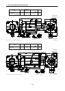
Section AA
Power supply connector layout
Top
Bottom
Top
Bottom
TopBottom
For forward rotation command
"Rotation direction"
For reverse rotation command
Top
Bottom
Earth
CE05-2A22-23P
M8 screw, depth 20
Motor flange direction
TUV plate
(Note 1)[Unit: mm]
Note 1. The dimensions without tolerances are reference dimensions.
2. This caution plate is attached to the 400V class motors only, not to the 200V class.