


7 - 120
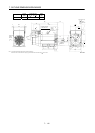
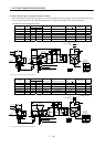
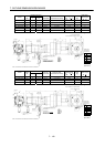
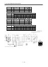
7. OUTLINE DIMENSION DRAWINGS
Variable Dimensions
Model
Output
[W]
LKL
Reduction
Gear Model
Reduction Ratio
(Actual Reduction Ratio)
Inertia Moment
J[
10
4
kg m
2
]
Mass
[kg]
Brake static
friction torque
[N
m]
HC-MFS23BG1 200 185 102.6 K9005 1/5(19/96) 0.289 3.9 1.3
HC-MFS23BG1 200 205 122.6 K9012 1/12(25/288) 0.333 4.5 1.3
HC-MFS23BG1 200 205 122.6 K9020 1/20(253/5000) 0.306 4.5 1.3
HC-KFS23BG1 200 185 102.6 K9005 1/5(19/96) 0.470 3.9 1.3
HC-KFS23BG1 200 205 122.6 K9012 1/12(25/288) 0.520 4.5 1.3
HC-KFS23BG1 200 205 122.6 K9020 1/20(253/5000) 0.490 4.5 1.3
Power supply
connector pin
connection list
1
2
3
4
Pin No. Application
Phase U
Phase V
Phase W
Earth
5
6
B1
B2
BC11903*
(BC11931*)
(Note)[Unit: mm]
20
5557-06R-210 (Receptacle)
5556PBTL (Female terminal)
With connector 1-172169-9
(AMP)
Arrow A
4
5
Protective tube
Motor plate
(Opposite side)
90
Logo plate
Power supply connector (Molex)
Encoder cable 0.3m
Motor plate
Caution
plate
Top
Bottom
Top
74
L
10.6
25.2
62
Arrow
A
9.9
41
10
1
2
4
5
For reverse rotation command
For forward rotation command
"Rotation direction"
1
1
4
1
0
0
4- 9
M6 threads,
depth 12
38.4
8
30 35
73
82h7
25h6
Bottom
Top
68
Power supply lead 4-AWG19 0.3m
Brake lead
2-0.3 0.3m
2
36
KL
2.7
42.8
Bottom
Top
TUV plate
Bottom
Note: The dimensions without tolerances are reference dimensions.
Banding band
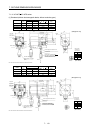
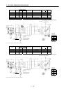
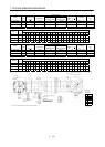
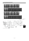
Variable Dimensions
Model
Output
[W]
LKL
Reduction
Gear Model
Reduction Ratio
(Actual Reduction Ratio)
Inertia Moment
J[
10
4
kg m
2
]
Mass
[kg]
Brake static
friction torque
[N
m]
HC-MFS43BG1 400 210 125.6 K9005 1/5(19/96) 0.344 4.4 1.3
HC-MFS43BG1 400 230 145.6 K9012 1/12(25/288) 0.388 5.0 1.3
HC-KFS43BG1 400 210 125.6 K9005 1/5(19/96) 0.660 4.4 1.3
HC-KFS43BG1 400 230 145.6 K9012 1/12(25/288) 0.710 5.0 1.3
Power supply
connector pin
connection list
1
2
3
4
Pin No.
Application
Phase U
Phase V
Phase W
Earth
5
6
B1
B2
BC11904*
(BC11932*)
(Note)[Unit: mm]
20
5557-06R-210 (Receptacle)
5556PBTL (Female terminal)
With connector 1-172169-9
(AMP)
Arrow A
4
5
Protective tube
Motor plate
(Opposite side)
90
Logo plate
Power supply connector (Molex)
Encoder cable 0.3m
Caution
plate
Top
Bottom
Top
74
L
10.6
25.2
62
Arrow
A
9.9
41
10
1
2
4
5
For reverse rotation command
For forward rotation command
"Rotation direction"
1
1
4
1
0
0
4- 9
M6 threads,
depth 12
38.4
8
30 35
73
82h7
25h6
Bottom
Top
68
Power supply lead 4-AWG19 0.3m
Brake lead
2-0.3 0.3m
2
36
KL
2.7
42.8
Bottom
Top
Motor plate
TUV plate
Bottom
Note: The dimensions without tolerances are reference dimensions.
Banding band