


7 - 228
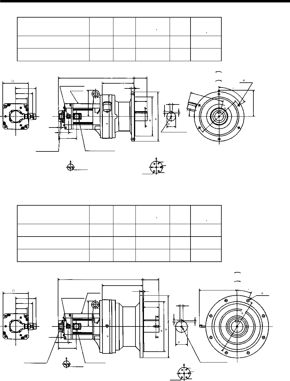
7. OUTLINE DIMENSION DRAWINGS
Model
Output
[kW]
Reduction
Ratio
Inertia Moment
WK
2
[oz in
2
]
Mass
[lb]
Brake static
friction torque
[oz
in]
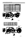
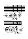
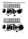
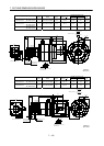
HC-SF502BG1
HC-SFS502BG1
HC-SFS5024BG1
5.0 1/11 674.68 222.7 6103
HC-SF502BG1
HC-SFS502BG1
HC-SFS5024BG1
5.0 1/17 652.81 222.7 6103
Power supply connector layout
CE05-2A24-10P
5.59
20.47
8.62
3.50
2.36
4.61
A
A
Motor plate
0.77
2.72
7.13
0.28
BC11033*
6
0
6- 0.43
0.43
Motor flange direction
0.71
U
V
W
C
D
B
E
A
G
F
Earth
Section A-A
M10 threads, depth 0.71
11.81
Encoder connector
MS3102A20-29P
Power supply connector
CE05-2A24-10P
7.13
3.20
Brake connector layout
MS3102A10SL-4P
Motor flange direction
B
A
Brake
4.90
Brake connector
MS3102A10SL-4P
0.79
0.16
3.35
10.63
13.39
8
.
9
8
1
2
.
2
1
6.93
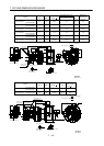
Bottom Top
[Side view of motor only]
[Unit: in]
"Rotation direction"
For reverse
rotation command
For forward
rotation command
1
5
(BC11844*)
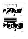
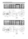
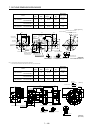
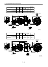
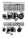
Model
Output
[kW]
Reduction
Ratio
Inertia Moment
WK
2
[oz in
2
]
Mass
[lb]
Brake static
friction torque
[oz
in]
HC-SF502BG1
HC-SFS502BG1
HC-SFS5024BG1
5.0 1/29 811.92 370.4 6103
HC-SF502BG1
HC-SFS502BG1
HC-SFS5024BG1
5.0 1/35 809.18 370.4 6103
HC-SF502BG1
HC-SFS502BG1
HC-SFS5024BG1
5.0 1/43 803.71 370.4 6103
5.59
22.95
10.98
4.33
3.15
4.61
A
A
Motor plate
0.77
2.72
0.35
BC11034*
8- 0.71
0.55
0.87
Power supply connector layout
CE05-2A24-10P
Motor flange direction
U
V
W
C
D
BE
A
G
F
Earth
Section A-A
14.57
Encoder connector
MS3102A20-29P
Power supply connector
CE05-2A24-10P
6.93
3.20
Brake connector layout
MS3102A10SL-4P
Motor flange direction
B
A
Brake
4.90
Brake connector
MS3102A10SL-4P
0.87
0.20
4.13
13.58
16.93
10.16
1
5
.
3
5
6.93
Bottom Top
[Side view of motor only]
[Unit: in]
"Rotation direction"
For reverse
rotation command
For forward
rotation command
1-M12 threads,
depth 0.95
(BC11845*)
2
2
.
5