


FX Series Programmable Controllers Related Information 9
9-28
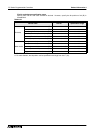
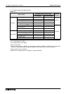
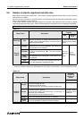
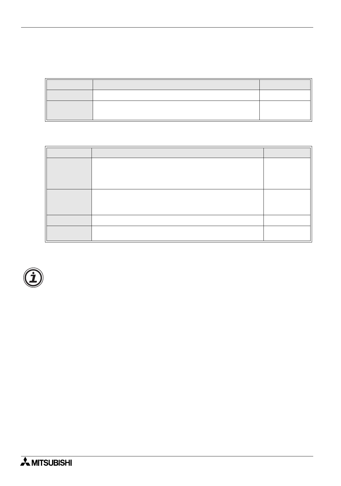
9.5.2 Screen specification registers (The table below indicates the case where D0 is
assigned.)
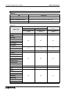
[25DU]
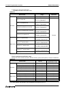
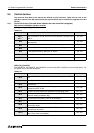
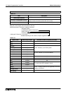
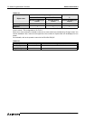
[30DU], [40DU], [40DU-TK], [50DU-TK], [F940GOT]
*1 D+6 is offered in the 50DU-TK and the F940GOT exclusively.
*2 D+7 is offered in the F940GOT exclusively.
Table 9.40:
Data register Contents of control Data direction
D+0
Specifies the screen No. to be displayed in the screen mode.
PC
→
DU
D+1
Stores the screen No. currently displayed in the screen mode.
(Stores "-1" while any mode other than the screen mode is
selected.)
DU
→
PC
Table 9.41:
Data register Contents of control Data direction
D+0
D+1
D+2
Specify the screen Nos. to be displayed in the screen mode.
D+0: Specifies the screen No. to be displayed. Or specifies the
screen No. treated as reference in screen overlay.
D+1, D+2: Specify the screen Nos. to be overlaid.
(Store "-1" while screens are not overlaid.)
PC
→
DU
D+3
D+4
D+5
Store the screen Nos. currently displayed in the screen mode.
(Store "-1" while any mode other than the screen mode is selected.)
D+3: Specifies the screen No. currently displayed.
D+4, D5: Store the screen Nos. overlaid.
DU
→
PC
D+6
Specifies a data file.
*1
PC
→
DU
D+7
Specifies the user ID which is treated as the input completion target
when the data on numerics and character codes is changed.
*2
PC
→
DU
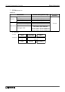
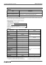
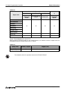
Data direction
Screen specification registers and control bit devices allow the DU to read the data written by the
DU to data registers (D) and auxiliary relays (M) in the PC and the data written by a program in the
PC.
PC
→
DU: Data is written by a program in the PC and read by the DU.
DU
→
PC: Data is written by the DU and used by a program in the PC.