


FX Series Programmable Controllers Menu Bar Function 6
6-31
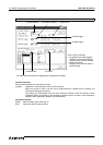
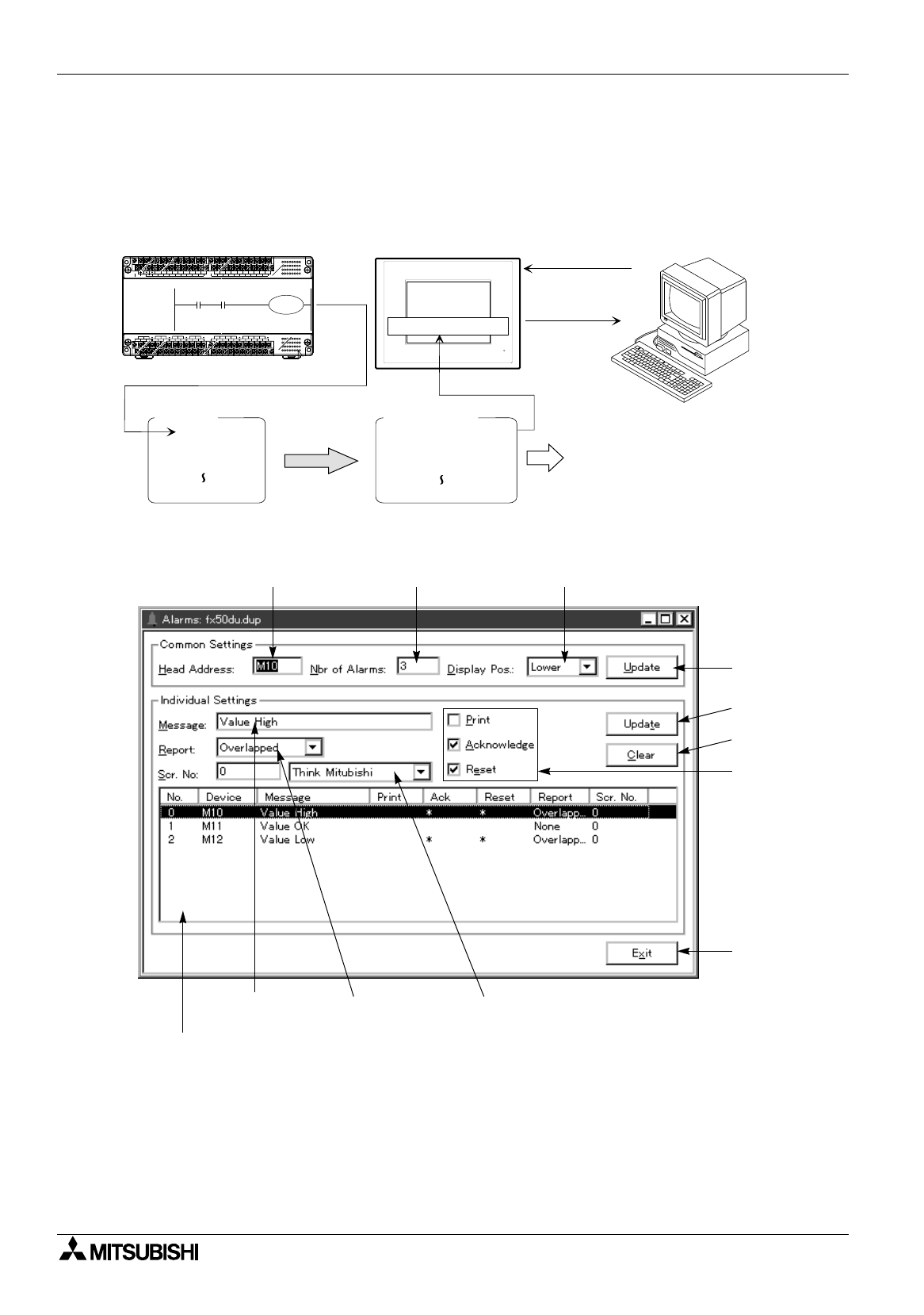
6.4.5 Creating and setting the alarm message
The “Alarms” command allows to create the alarm message to be displayed in the DU. By setting the screen
changeover, printout to the printer, etc., this command can offer the alarm message and the action
corresponding to the bit device from the PC.
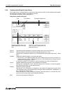
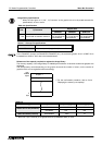
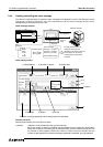
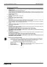
Alarm message function
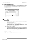
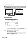
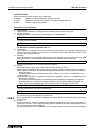
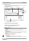
Alarm setting window
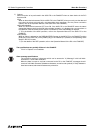
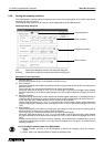
Common set items
Set the items shared by the entire alarm function.
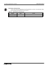
a) Update Updates to a value entered to each common set item.
When the number of alarms is modified and the Update button is clicked, the confirmation
dialog box is opened. This dialog box is displayed when the value entered is different from
the number of data registered. When the number of alarms entered is smaller than the
number of data registered, excessive messages registered are deleted. Pay rigid attention.
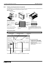
Alarm messages
are registered.
POWER
SG
N 24+24+ RUNX1X3X5X7X11X13
COMCOMX0 X2 X4 X6 X10 X12 X14 X16 X20X22 X24 X26 X30 X32X34 X36
X15 X17 X21 X23 X25 X27 X31 X33 X35 X37L
AC85~264V
Y0 Y2
COM1Y1 Y3
Y4 Y6
COM2Y5 Y7 COM3Y11 Y13COM4Y15 Y17
Y10Y12 Y14Y16 Y20 Y22Y24 Y26 Y30 Y32Y34 Y36
COM5Y21 Y23 Y25Y27 COM6Y31Y33 Y35Y37
DU
Personal computer
PC
Error messages
Error No. 1 occurred.
Error No. 2 occurred.
Error No. 3 occurred.
Error No. 50 occurred.
M100
becomes
ON.
Displayed
Error No.1 occurred.
The date, the time and error
messages are stored and
displayed as the history in the DU.
Or the history can be read by
and displayed in the personal
computer.
Inside DU
Correspondence
Assigned
The alarm
history is
read.
M100
M101
M102
M149
M100
2) Number of Alarms 3) Display Pos.
4) Message
7) Options
5) Report 6) Scr No.
1) Head Address
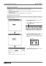
b)
c)
a)
d)
The alarm message registered and the setting status are displayed.