


FX Series Programmable Controllers Object Function Description 8
8-35
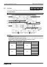
The word devices are drawn as line graphs using the data "Number of line graphs (1 to 4) x 3) Ticks
Horizontal" (when the data size is 16 bits).
When "7) Data Size" is set to "32 bits", the number of required word devices becomes twice of the above.
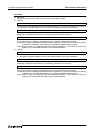
2 ) Minimum Value and Maximum Value
Specify the range in which the data assigned to the word devices specified in 1) Word Device is sampled
and displayed in the vertical axis. (When a value exceeds this range, the displayed trend graph is
discontinued.)
Direct: Enter a numeric.
7) Data size = 16 bits: -32,768 to +32,767
32 bits: -2,147,483,648 to +2,147,483,647
Indirect: Enter a word device (T, C, D, V or Z) or a data file No.
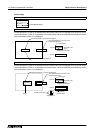
3 ) Ticks Horizontal and Ticks Vertical
Enter the number of divisions in the horizontal and vertical axes of the graph respectively.
Available number of divisions: 0, 2 to 50 (divided into equal portions)
When "0" is entered, the scale is not displayed.
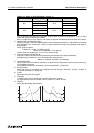
4 ) Undisplayed Value
When a value of the word device specified in 1) Word Device is equivalent to the input value set here, it
is not plotted in the graph.
The available values are in accordance with the size specified in 7) Data Size.
5 ) Shown Devices
Select the number of line graphs to be displayed and the line type ("Unbroken", "Broken", "Dotted" or
"Long and short dash") of each graph.
6 ) Frame
Select the fame color of the graph.
7 ) Data Size
"1) Word Device" can be handled as a numeric value of 16 or 32 bits.
For high-speed counters from C200 in the FX Series PLC, select "32 bits".
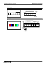
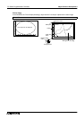
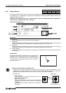
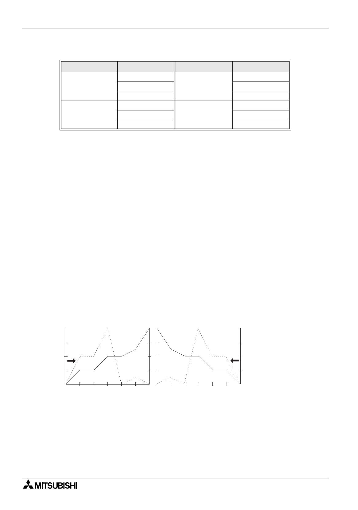
8 ) Direction
Select the data display start direction.
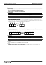
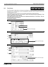
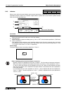
Table:8.12 When "3) Ticks Horizontal" is set to "3"
5) Shown Devices 1) Word Device 5) Shown Devices 1) Word Device
No.1
D+0
No.3
D+6
D+1 D+7
D+2 D+8
No.2
D+3
No.4
D+9
D+4 D+10
D+5 D+11
R i g h t ( f r o m t h e r i g h t )
L e f t ( f r o m t h e l e f t )