


FX Series Programmable Controllers Related Information 9
9-15
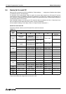
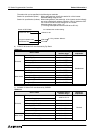
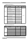
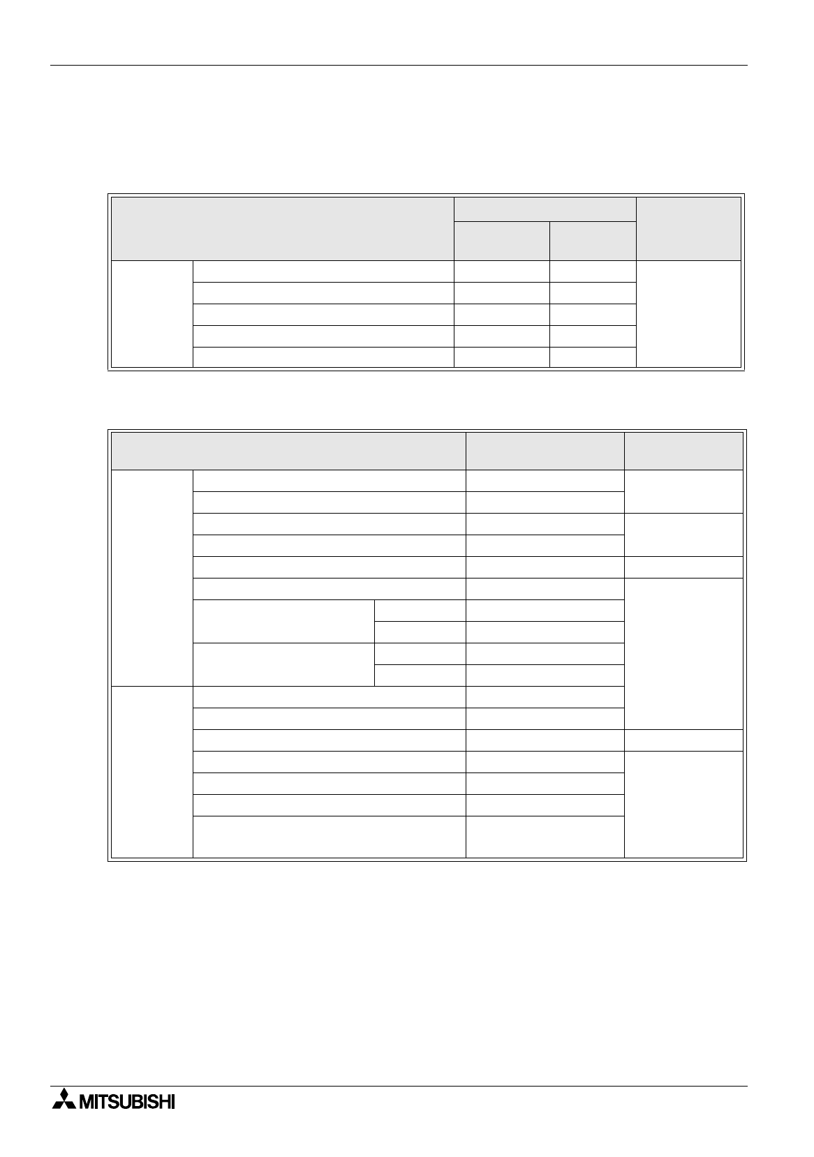
Restriction in setting monitor in computer link for A Series
When a computer link unit for the A Series PLC is mounted to the CPU in the QnA Series PLC and the GOT-
F900 is connected to the unit, the allowable setting monitor range becomes equivalent to that for the AnA
CPU, and the restriction shown in the table below is imposed (due to limitation in the computer link).
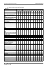
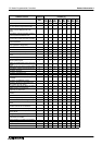
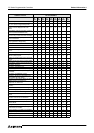
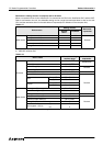
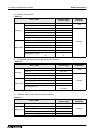
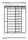
2 ) MELSEC A Series PLC
*1 In the computer link connection, index registers cannot be written.
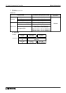
Table 9.17:
Device name
Setting monitor
Device No.
expression
GOTRE-
PACK
DU/WIN-E
Word device
Timer (current value)
0 to 255
Decimal
Timer (preset value)
Counter (current value)
0 to 255
Counter (preset value)
File register
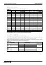
Table 9.18:
Device name
Allowable setting
monitor range
Device No.
expression
Bit device
Input (X) X0 to X0FFF
Hexadecimal
Output (Y) Y0 to Y0FFF
Internal relay (M) M0 to M8191
Decimal
Annunciator (F) F0 to F2047
Link relay (B) B0 to B1FFF Hexadecimal
Special internal relay (M) M9000 to M9255
Decimal
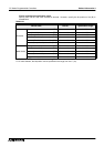
Timer
Contact (T) T0 to T2047
Coil (T) T0 to T2047
Counter
Contact (T) C0 to C1023
Coil (T) C0 to C1023
Word device
Data register (D) D0 to D8191
Special data register (D) D9000 to D9255
Link register (W) W0 to W1FFF Hexadecimal
Timer (current value) (T) T0 to T2047
Decimal
Counter (current value) (C) C0 to C1023
File register (R) R0 to R8191
Index register*1 (Z) (V)
(Z) Z
(V) V