


FX Series Programmable Controllers Related Information 9
9-27
Handy GOT
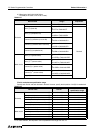
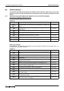
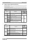
• Wire the four operation switches on the panel face to inputs of the PLC.
• For LEDs of the operation switches, assign the head device No. to the common screen using the "Output
Indicator" object.
When the head device No. is set to M11 using the "Output Indicator" object, four auxiliary relays M11 to M14
are occupied.
Pay attention so that the control bit devices shown above do not overlap M10 to M13.
For the details, refer to "8.16 Setting dedicated to handy GOT".
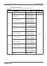
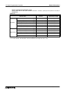
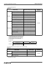
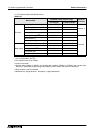
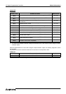
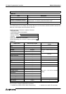
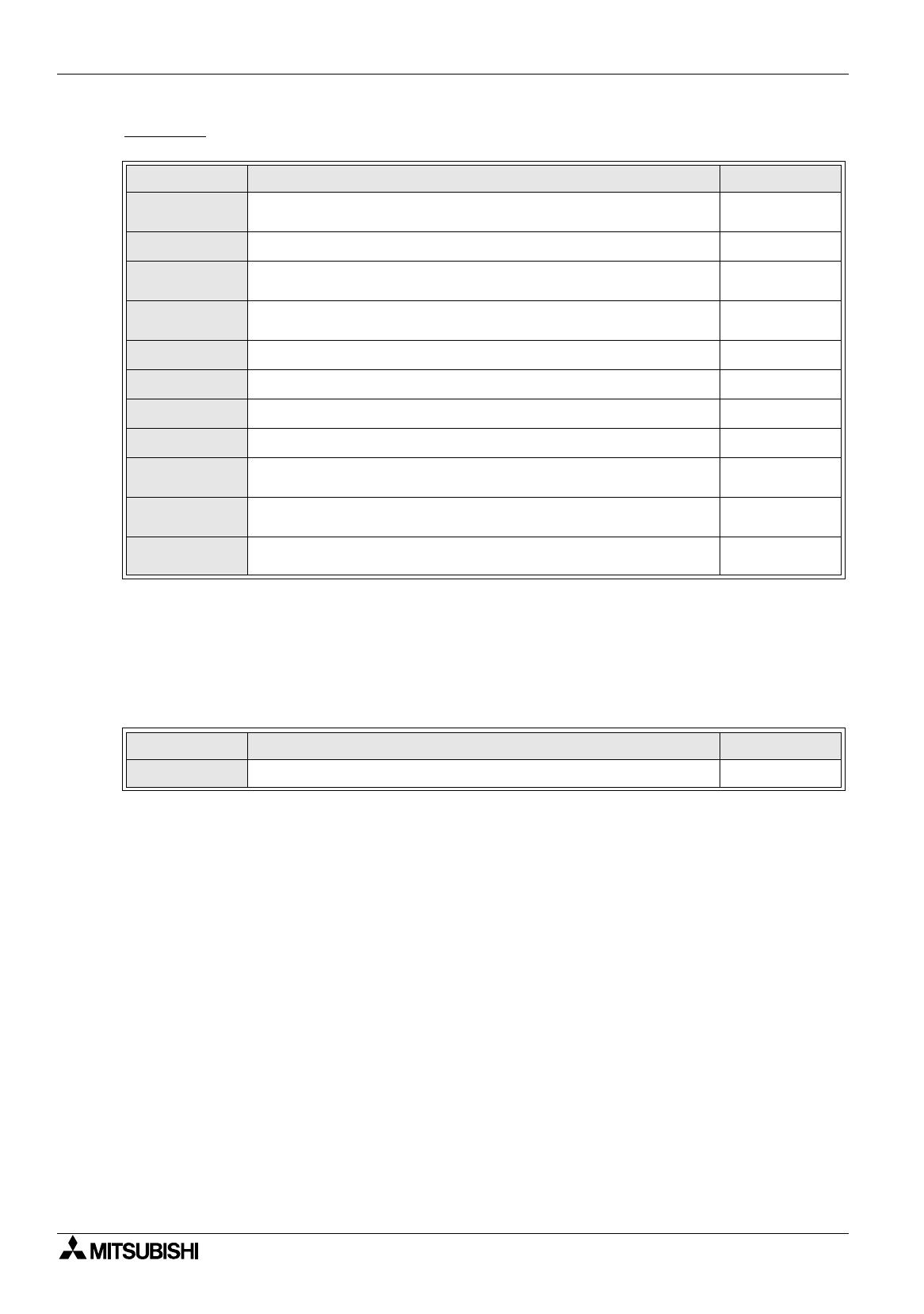
Table 9.38:
Auxiliary relay Contents of control Data direction
M+0
Clears the alarm history when a bit device is changed from OFF to
ON.
PC
→
DU
M+1
Remains ON while a device assigned for alarm is turned ON.
DU
→
PC
M+2
When ON, extinguishes the backlight of the display screen after a
specified time.
PC
→
DU
M+3
Clears the data sampled in the sampling mode when a bit device is
changed from OFF to ON.
PC
→
DU
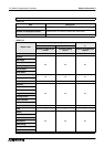
M+4
Remains ON while sampling is executed in the sampling mode.
DU
→
PC
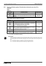
M+5
Turns ON as a numeric setting completion flag.
DU
→
PC
M+6
Turns ON when the battery of the handy GOT is decreased.
DU
→
PC
M+7
Remains ON while the grip switch is turned ON.
DU
→
PC
M+8
Unused (In V 3.00 and later of the handy GOT, turns ON to indicate
that a bar code is input.)
DU
→
PC
M+9
Unused (In V 3.00 and later of the handy GOT, turns ON to indicate
that bar code input is invalid.)
DU
→
PC
M+10
Unused (In V 3.00 and later of the handy GOT, turns ON to indicate
that read of a bar code is completed.)
DU
→
PC
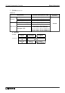
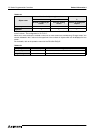
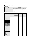
Table 9.39:
Auxiliary relay Contents of control Data direction
M11 to M14
LEDs of operation switches SW1 to SW4
PC
→
DU