


FX Series Programmable Controllers Object Function Description 8
8-27
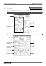
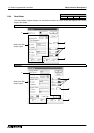
Input items
1 ) Word Device
Enter the top word device in the PC.
Consecutive word devices from the one specified here as many as the number set in 2) Nbr Of Devices
are to be displayed as bar graphs respectively.
A data register (D) exclusively can be entered here.
2 ) Nbr of Devices
Enter the number of word devices (1 to 6) to be displayed as bar graphs.
Enter the number of word devices (1 to 8) to be displayed as bar graphs.
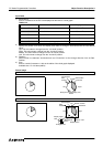
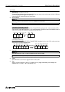
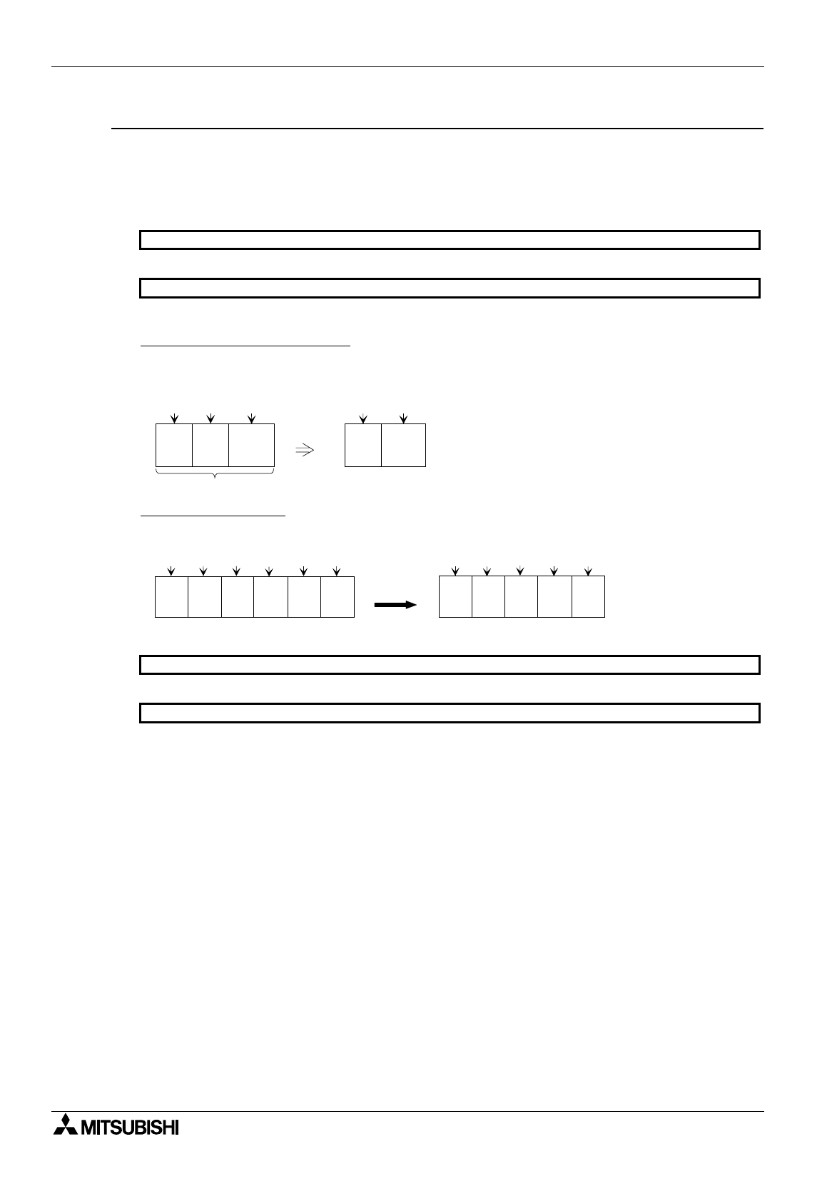
In the case of black-and-white LCD
Enter "2" when the DU type is FX-50DU-TK or F940GOT-LWD (equipped with a black-and-white LCD).
If the value of a word device becomes "0", it is not displayed as a graph and cannot be identified because
only two colors (black and white) are available as the data colors.
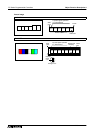
In the case of color LCD
When the DU type is FX-50DU-TKS or F940GOT-SWD (equipped with a color LCD), make sure that a
same color is not used in adjacent area.
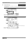
3 ) Data color
Select the level color of Bar 1 to Bar 6 respectively from the color pallet.
Select the level color of Bar 1 to Bar 8 respectively from the color pallet.
4 ) Frame
Select the frame color of the bar graphs from the color pallet.
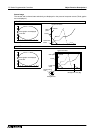
5 ) Size
Enter a numeric (increment: 1 dot) to "W" (width) and "H" (height) respectively as the display size.
Available size: 2
×
2 dots ~ 320
×
240 dots (W
×
H)
50DU-TK
F940GOT
When data
No. 2
becomes "0"
Black
White
Number of data = 3
Data 1
Data 2
Data 3
Data 1
Data 2
Black Black Black
When Data 3
becomes "0"
Data1
Red
Blue
Black
Red
Blue
Data2
Blue
White
Purple
White
Purple
Data3
Data6
Data4 Data5
Data1
Data2
Data4
Data5 Data6
Blue
50DU-TK
F940GOT