


FX Series Programmable Controllers Related Information 9
9-14
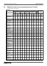
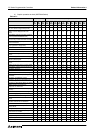
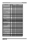
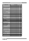
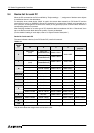
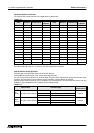
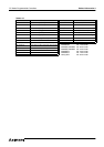
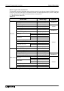
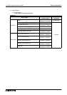
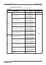
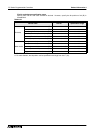
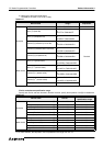
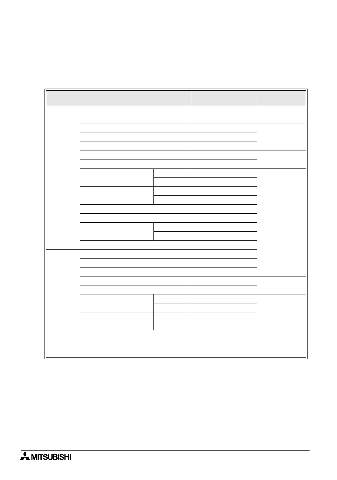
Device range of each connected PLC
This paragraph shows the allowable maximum device range which can be set using the DU/WIN-E software
(in the DU or the GOT main body) in accordance with each connected equipment (PLC). When reading this
manual, adopt the device range in accordance with the connected PLC.
1 ) MELSEC Q/QnA Series PLC
*1 Targets are file registers in a block changed over by the RSET instruction.
Table 9.16:
Device name
Allowable setting
monitor range
Device No.
expression
Bit device
Input (X) X0 to X1FFF
Hexadecimal
Output (Y) Y0 to Y1FFF
Internal relay (M) M0 to M32767
DecimalLatch relay (L) L0 to L32767
Annunciator (F) F0 to F32767
Link relay (B) B0 to B7FFF
Hexadecimal
Special link relay (SB) SB0 to SB7FF
Timer (T)
Contact T0 to T32767
Decimal
Coil
Counter (C)
Contact C0 to C32767
Coil
Special internal relay (M)
Special relay (SM) SM0 to SM2047
Integrating timer (ST)
Contact SS0 to SS32767
Coil SC0 to SC32767
Step relay (S) S0 to S32767
Word device
Data register (D) D0 to D32767
Special data register (D)
Special register (SD) SD0 to SD32767
Link register (W) W0 to W7FFF
Hexadecimal
Special link register (SW) SW0 to SW7FF
Timer (T)
Counter (C) T0 to T32767
Decimal
Current value
Preset value
Counter (C) C0 to C32767
Current value
Integrating timer (current value) (SN) SN0 to SN32767
File register (R)
R0 to R32767
*1
Index register (Z) Z