


FX Series Programmable Controllers
Object Function Description 8
8-42
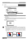
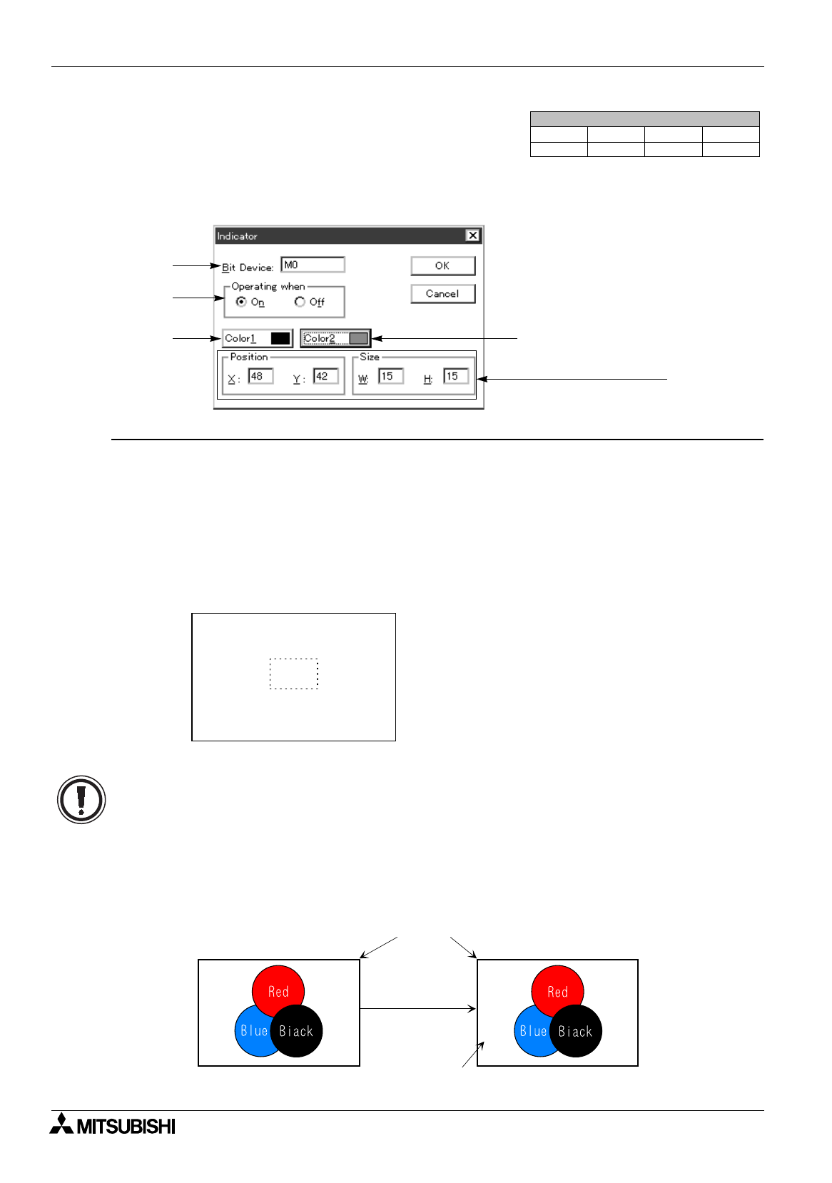
8.4.3 Indicator
When a color within the preset indicator area becomes equivalent to a specified color by turning on/off of the
specified bit device in the PC, the "Indicator" object allows to replace such a color within the preset indicator
area with the other specified color.
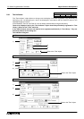
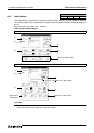
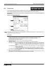
Input items
1 ) Bit Device
Enter a bit device in the PC which turns on/off the indicator.
2 ) Operating when
Specify the logic to replace the display color by "ON" or "OFF" of the bit device specified in 1) Bit Device.
3 ) Color 1 and Color 2
The "Indicator" object replaces a color (including character color, line color, rectangle color, circle color
and background color of entire screen) within the indicator area which has become equivalent to "Color
1" or "Color 2" with "Color 2" or "Color 1" respectively.
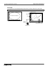
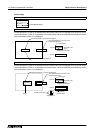
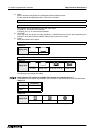
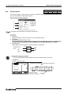
Screen image
The preset indicator area is secured by dotted line of "Color 1".
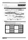
Screen List Window
Objects
Screen
Keys
Header
""
1)
3)
2)
Refer to the "Text" object.
3)
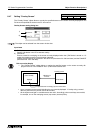
While the indicators are turned off
Indicator area
While the indicators are turned on
Remains in the same color.
Color 2=Red
Color 1=Black
Bit device is
turned on.
Rule of replacing colors when the indicator is turned on
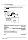
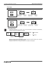
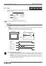
Objects in the DU are displayed in the order of creation. The first object is located at the bottom.
When the indicator created at first (located at the bottom) is turned on, a color equivalent to "Color 1"
or "Color 2" within the indicator area is replaced by the unit of dot. When an other indicator is located
above the first indicator, color is replaced in the upper indicator in accordance with color replacement
in the lower indicator.
In an example below, the color equivalent to "Color 2" (= red) is replaced with the color specified as
"Color 1" (= black). The color equivalent to "Color 1" (= black) is replaced with the color specified as
"Color 2" (= red).