


FX Series Programmable Controllers Related Information 9
9-16
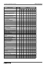
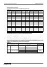
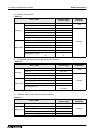
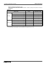
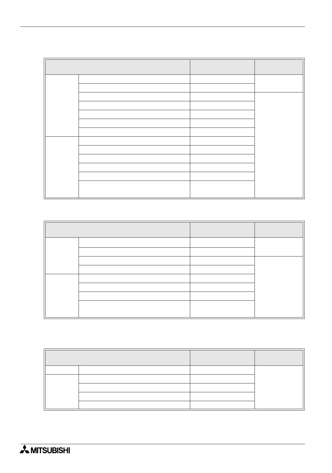
3 ) MELSEC FX Series PLC
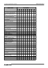
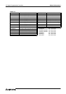
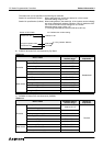
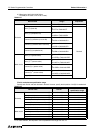
4 ) FX Series GM positioning function (GM CPU direct connection)
*1 Devices cannot be written.
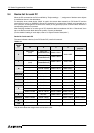
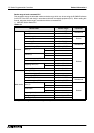
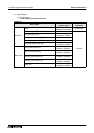
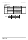
5 ) FREQROL Series inverter (INV CPU direct connection)
"
#
" indicates the station No. of the monitored inverter.
Table 9.19:
Device name
Allowable setting
monitor range
Device No.
expression
Bit device
Input relay (X) X0000 to X0377
Octal
Output relay (Y) Y0000 to Y0377
Auxiliary relay (M) M0000 to M3071
Decimal
Special auxiliary relay (M) M8000 to M8255
State (S) S0000 to S0999
Timer contact (T) T000 to T255
Counter contact (C) C000 to C255
Word device
Timer (current value) (T) T000 to T255
Counter (current value) (C) C000 to C255
Data register (D) D000 to D0999
RAM file register (D) D1000 to D7999
Special data register (D) D8000 to D8255
Index register*1 (Z) (V)
(Z) Z
(V) V
Table 9.20:
Device name
Allowable setting
monitor range
Device No.
expression
Bit device
Input (X)
*1
X0 to X377
Octal
Output (Y) Y0 to Y67
Internal relay (M) M0 to M511
Decimal
Special auxiliary relay (SM) M9000 to M9175
Word device
Data register (D) D0 to D8191
Special data register (SD) D9000 to D3999
File register (R) D4000 to D6999
Index register (Z, V)
Z (32 bits)
V (16 bits)
Table 9.21:
Device name
Allowable setting
monitor range
Device No.
expression
Bit device Control status (S) S0:
#
to S7:
#
Decimal
Word device
Alarm code (A) A0:
#
to A7:
#
Parameter (Pr) Pr0:
#
to Pr993:
#
Program operation (PG) PG0:
#
to PG89:
#
Special parameter (SP) SP108:
#
to SP127:
#