


FX Series Programmable Controllers Object Function Description 8
8-19
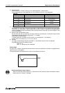
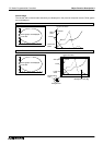
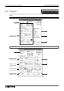
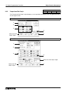
2 ) Minimum Value and Maximum Value
Specify the range in which the data assigned to the word device specified in 1) Word Device is read in
the sampling cycle specified in 4) Sample. Cycle and displayed in the vertical axis. The minimum value is
regarded as 0% and the maximum value is regarded as 100% in the graph. (When a value exceeds this
range, the displayed trend graph is discontinued.)
Enter a numeric.16 bits: -32768 to +32767
Direct: Enter a numeric directly.
( 7) Data Size16 bits: -32,768 to +32,767
32 bits: -2,147,483,648 to +2,147,483,647)
Indirect: Enter a word device (T, C, D, V or Z).
3 ) Ticks Vertical
Enter the number of scales in the horizontal and vertical axes of the graph respectively.
Available number of scales: 2 to 10 (divided into equal portions)
Available number of divisions: 0, 2 to 50 (divided into equal portions)
When "0" is selected, the scale is not displayed.
4 ) Sampl. Cycle (s)
Set the time interval in which the word devices in the PC specified in 1) Word Device are sampled.
Cycle: 1 to 65,535 (seconds) (increment: 1)
5 ) Shown Devices
Select the line type (None, Unbroken, Broken, Dotted, Dashed) and the line color. When "None" is
selected, the line is not displayed.
6 ) Bg and Frame
Set the display colors of the graph.
Select the horizontal/vertical axis color of the graph.
Select the background color and the horizontal/vertical axis color of the graph.
7 ) Data Size
Select the data size of 1) Word Device between "16 bits" and "32 bits".
When a high speed counter or 32-bit counter is set to 1) Word Device, make sure to select "32 bits".
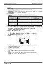
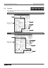
8 ) Direction
Select the trend graph plotting direction (right or left).
9 ) Store in Memory
Set whether or not the sampled data is to be stored in the memory in the F940GOT.
Stored (with check mark):Even after the screen is changed over and returned to the current screen, the
trend graph is displayed with previous values.
Not stored (without check mark):After the screen is changed over and returned to the current screen, the
trend graph is displayed with new values.
10 ) Clear Trigger
Set the bit device to clear the memory when 9) Memory Store is set effective (with a check mark).
11 ) Execution Condition
Select the condition to clear the memory between "OFF
→
ON (rising)" and "ON
→
OFF (falling)" of the
bit device specified in 10) Clear Trigger when 9) Memory Store is set effective.
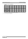
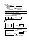
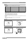
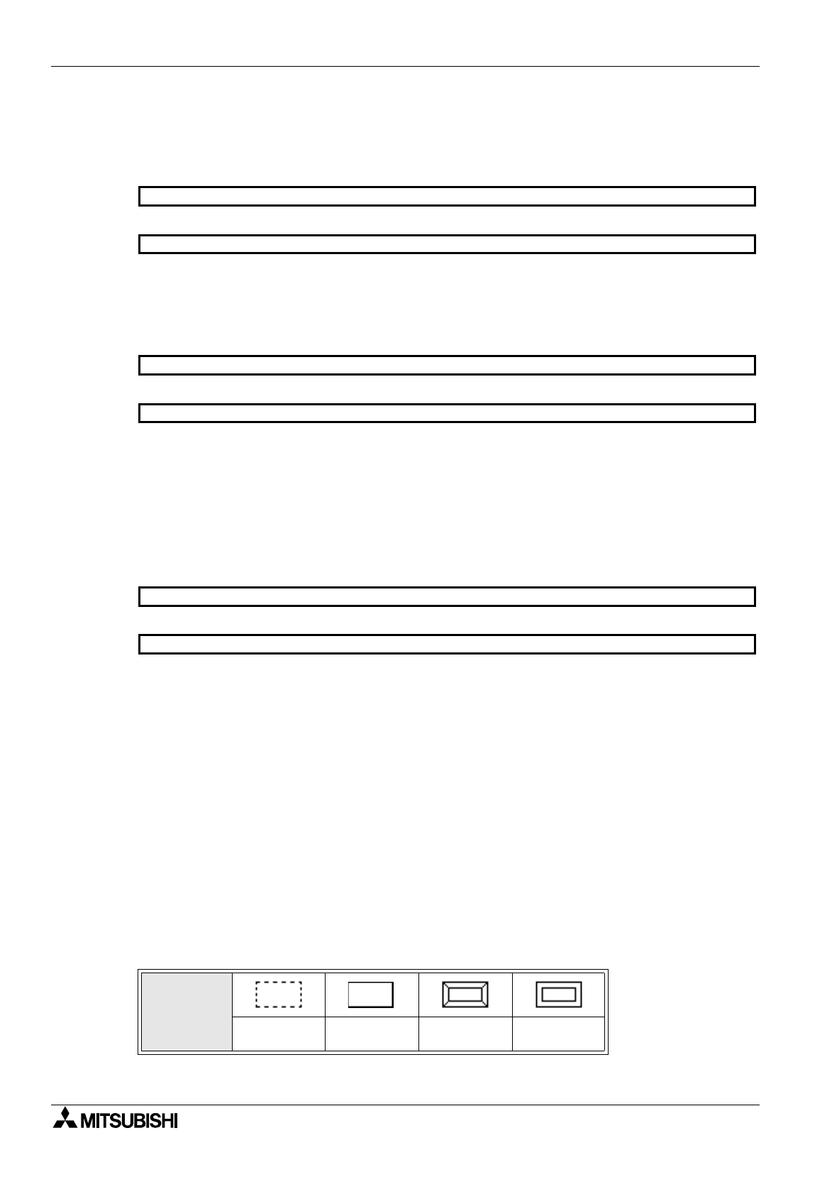
12 ) Frame Type
Select the form of a frame displayed around the trend graph.
* When "No frame" is selected, a dotted-line frame is displayed in the DU-WIN software, and no frame is
displayed in the DU and the F940GOT.
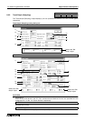
Table:8.9
Display form
No frame Single frame
Double frame
(keyboard)
Double frame
(trimmed)
50DU-TK
F940GOT
50DU-TK
F940GOT
50DU-TK
F940GOT