


FX Series Programmable Controllers Related Information 9
9-24
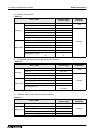
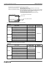
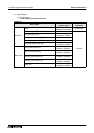
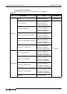
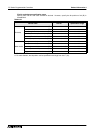
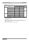
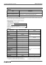
11 ) FP Series by Matsushita Electric Works
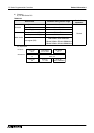
Pulse relay (P) and index registers (IX, IY and I) are not supported.
*1 It is not supported in the FP0.
*2 It is supported only in the FP2SH.
*3 It cannot be written.
*4 Special relays (R9000 to R910F) and special data registers (DT9000 to DT9255) are included also.
However, if special data registers begin with D9000 in the FP Series, they cannot be accessed.
*5 Only the bank 0 can be accessed.
*6 Bit device No. (3-digit decimal) + Bit position (1-digit hexadecimal)
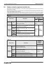
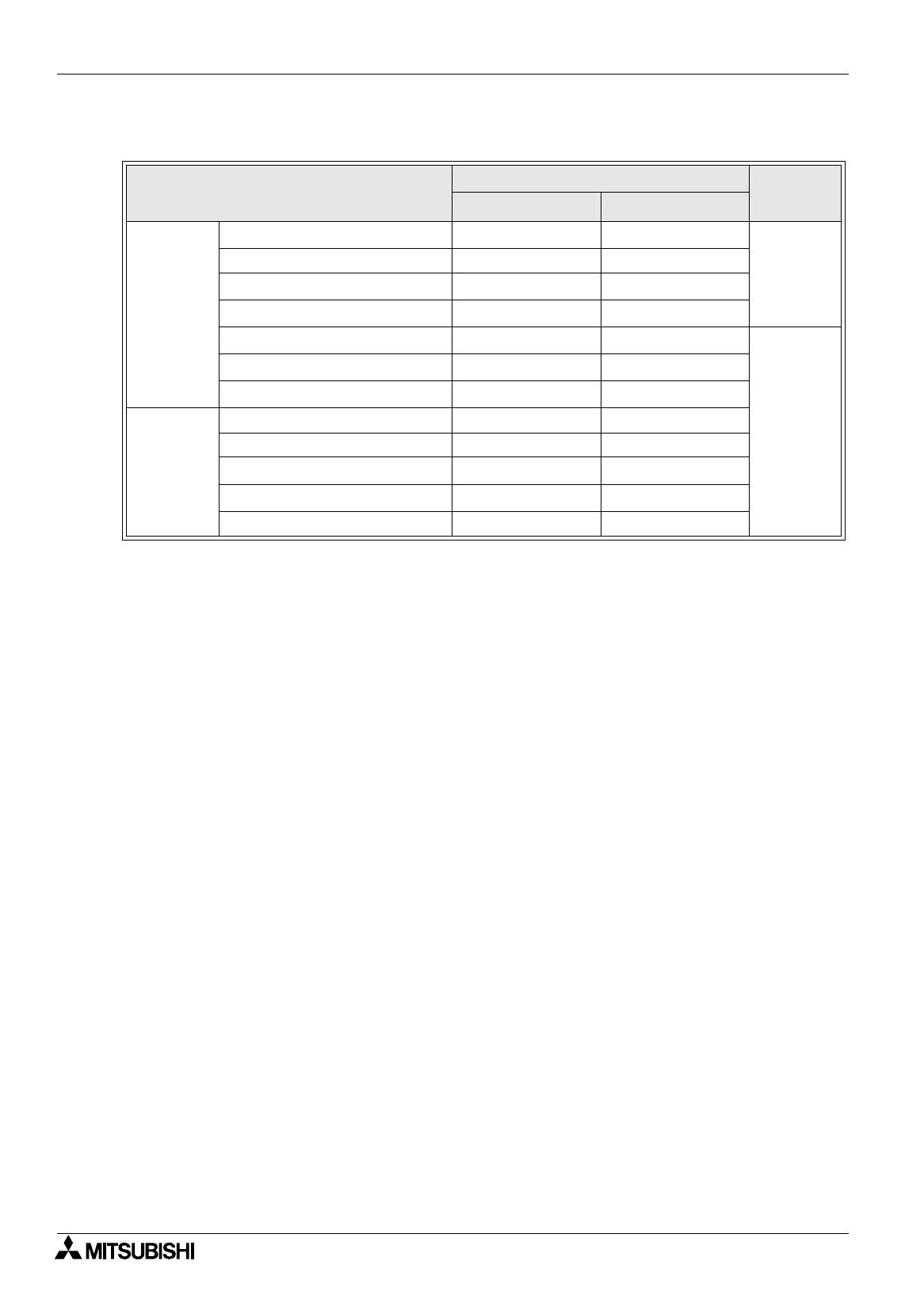
Table 9.32:
Device name
Allowable setting monitor range
Device No.
expression
GT Designer FX-PCS-DU/WIN-E
Bit device
Input relay (X)
*3
X0000~X511F X0000~X511F
Decimal
*6
Output relay (Y) Y0000~Y511F Y0000~Y511F
Internal relay (R)
*4
R0000~R910F R0000~R910F
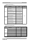
Link relay (L)
*1
L0000~L639F L0000~L639F
Error alarm relay (E)
*2*3
E0~E2047 E0~E2047
Decimal
Timer contact (T)
*3
T0~T3071 T0~T3071
Counter contact (C)
*3
C0~C3071 C0~C3071
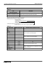
Word device
Timer/counter elapsed value (EV) EV0~EV3071 EV0~EV3071
Timer/counter set value (SV) SV0~SV3071 SV0~SV3071
Data register (DT)
*4
DT0~DT16383 DT0~DT16383
Link register (LD)
*1
LD0~LD8447 LD0~LD8447
File register (FL)
*1*5
FL0~FL32764 FL0~FL32764