


3 - 52
3 POSITIONING DEDICATED SIGNALS
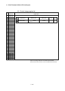
3.2.2 Control change registers
This area stores the JOG operation speed data.
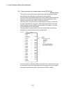
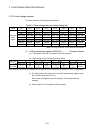
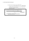
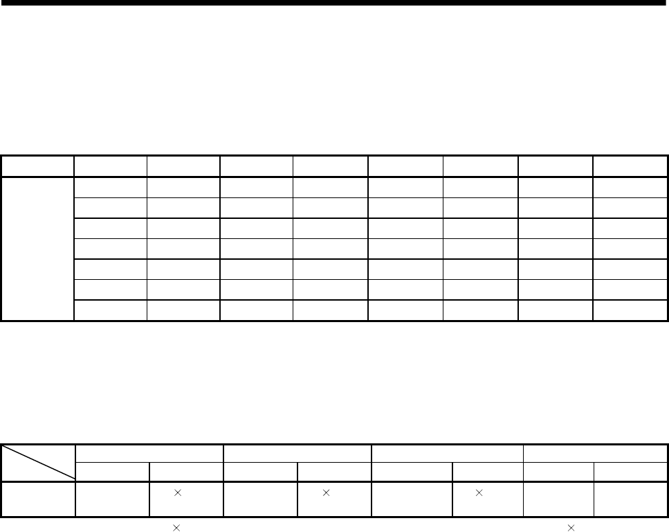
Table 3.1 Data storage area for control change list
Name Axis 1 Axis 2 Axis 3 Axis 4 Axis 5 Axis 6 Axis 7 Axis 8
D641, D640 D643, D642 D645, D644 D647, D646 D649, D648 D651, D650 D653, D652 D655, D654
Axis 9 Axis 10 Axis 11 Axis 12 Axis 13 Axis 14 Axis 15 Axis 16
D657, D656 D659, D658 D661, D660 D663, D662 D665, D664 D667, D666 D669, D668 D671, D670
Axis 17 Axis 18 Axis 19 Axis 20 Axis 21 Axis 22 Axis 23 Axis 24
D673, D672 D675, D674 D677, D676 D679, D678 D681, D680 D683, D682 D685, D684 D687, D686
Axis 25 Axis 26 Axis 27 Axis 28 Axis 29 Axis 30 Axis 31 Axis 32
JOG speed
setting
register
D689, D688 D691, D690 D693, D692 D695, D694 D697, D696 D699, D698 D701, D700 D703, D702
(Note): The range of axis No.1 to 8 is valid in the Q172HCPU.
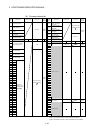
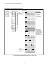
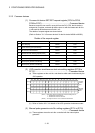
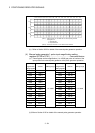
(1) JOG speed setting registers (D640+2n) ....…….. Command device
(a) This register stores the JOG speed at the JOG operation.
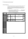
(b) Setting range of the JOG speed is shown below.
mm inch degree PLS Unit
Item
Setting range Unit Setting range Unit Setting range Unit
(Note)
Setting range Unit
JOG speed
1 to
600000000
10
-2
[mm/min]
1 to
600000000
10
-3
[inch/min]
1 to
2147483647
10
-3
[degree/min]
1 to
2147483647
[PLS/s]
(Note) : When the " speed control 10 multiplier setting for degree axis" is set to "valid" in the fixed parameter, the unit is " 10
-2
[degree/min] ".
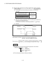
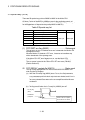
(c) The JOG speed is the value stored in the JOG speed setting registers when
the JOG start signal turns off to on.
Even if data is changed during JOG operation, JOG speed cannot be
changed.
(d) Refer to Section 6.21 for details of JOG operation.