


5 - 18
5 SERVO PROGRAMS FOR POSITIONING CONTROL
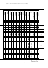
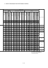
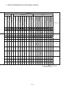
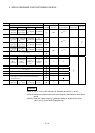
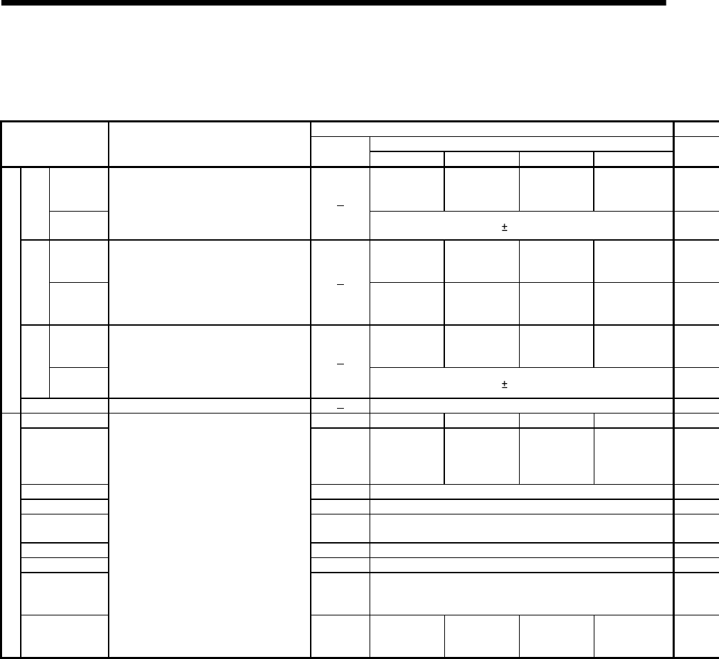
Table 5.3 Positioning data (Continued)
Setting value using a peripheral device
Setting range
Name Explanation
Default
value
mm inch degree PLS
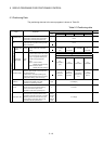
Absolute
data method
-214748364.8 to
214748364.7
[
µ
m]
-21474.83648
to 21474.83647
0 to 359.99999
-2147483648
to 2147483647
Auxiliary
point
Incremental
data method
• Set at the auxiliary point-specified circular
interpolation.
0 to
2147483647
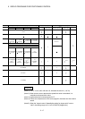
Absolute
data method
0.1 to
429496729.5
[
µ
m]
0.00001 to
42949.67295
0 to 359.99999 1 to 4294967295
Radius
Incremental
data method
• Set at the radius-specified circular
interpolation.
• The sitting ranges depending on the
positioning nethod is shown to the right.
0.1 to
214748364.7
[
µ
m]
0.00001 to
21474.83647
0.00001 to
21474.83647
1 to 2147483647
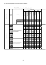
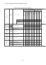
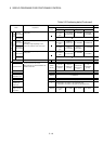
Absolute
data method
-214748364.8 to
214748364.7
[
µ
m]
-21474.83648
to 21474.83647
0 to 359.99999
-2147483648
to 2147483647
Central point
Incremental
data method
• Set at the central point-specified circular
interpolation.
0 to
2147483647
Circular Interpolation
Number of pitches • Set at the helical interpolation.
0 to 999
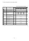
Control unit 3 0 1 2 3
Speed limit value
200000
[PLS/s]
0.01 to
6000000.00
[mm/min]
0.001 to
600000.000
[inch/min]
0.001 to
2147483.647
[degree/min]
(Note-5)
1 to
2147483647
[PLS/s]
Acceleration time 1000[ms] 1 to 65535[ms]
Deceleration time 1000[ms] 1 to 65535[ms]
Rapid stop
deceleration time
1000[ms] 1 to 65535[ms]
S-curve ratio 0[%] 0 to 100[%]
Torque limit value 300[%] 1 to 1000[%]
Deceleration
processing on
STOP input
0
0: Deceleration stop based on the deceleration time
1: Deceleration stop based on the rapid stop deceleration time
Parameter block
Allowable error
range for circular
interpolation
• It can be set only items to be changed of the
specified parameter block data.
• Refer to Section 4.3 "Parameter Block" for
details of each data.
100[PLS]
0 to 10000.0
[
µ
m]
0 to 1.00000 0 to 1.00000 0 to 100000