


3 - 20
3 POSITIONING DEDICATED SIGNALS
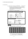
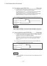
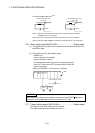
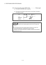
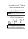
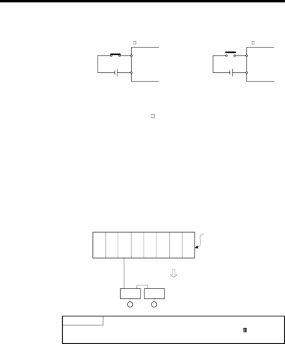
2) Servo amplifier input use
(Note-3)
DOG/CHANGE signal : ON
DOG/CHANGE
DI3
DICOM
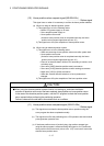
DOG/CHANGE signal : OFF
DOG/CHANGE
DI3
DICOM
MR-J3- B MR-J3- B
(Note-1): Refer to the "Q173HCPU/Q172HCPU Motion controller Programming Manual
(COMMON)" for an external signal.
(Note-2): Refer to the "Q173HCPU/Q172HCPU User’s Manual" for a pin configuration.
(Note-3): Refer to the "MR-J3-
B Servo Amplifier Instruction Manual" for a pin configuration.
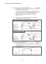
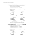
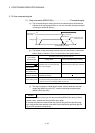
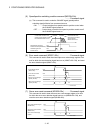
(16) Servo ready signal (M2415+20n) ..............................Status signal
(a) This signal turns on when the servo amplifiers connected to each axis are in
the READY state.
(b) This signal turns off in the following cases.
• M2042 is off
• Servo amplifier is not installed
• Servo parameter is not set
• It is received the forced stop input from an external source
• Servo OFF by the servo OFF command (M3215+20n) ON
• Servo error occurs
Refer to APPENDIX 1.4 "Servo errors" for details.
Q61P Q02H
CPU
Q38B
Communication is normal
Servo ready signal : ON
M
Q172
LX
Q172H
CPU
AMP
M
AMP
POINT
When the part of multiple servo amplifiers connected to the SSCNET becomes a
servo error, only an applicable axis becomes the servo OFF state.
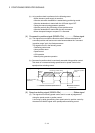
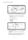
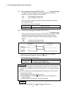
(17) Torque limiting signal (M2416+20n) ..........................Status signal
This signal turns on while torque limit is executed.
The signal toward the torque limiting axis turns on