


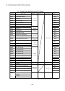
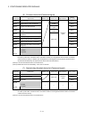
3 - 18
3 POSITIONING DEDICATED SIGNALS
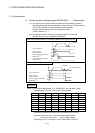
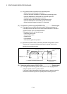
(12) FLS signal (M2411+20n)
(Note-1)
...................................Status signal
(a) This signal is controlled by the ON/OFF state for the upper stroke limit
switch input (FLS) of the Q172LX/servo amplifier.
• Upper stroke limit switch input OFF ...... FLS signal: ON
• Upper stroke limit switch input ON ........ FLS signal: OFF
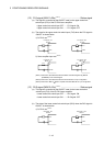
(b) The state for the upper stroke imit switch input (FLS) when the FLS signal is
ON/OFF is shown below.
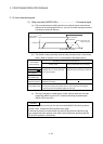
1) Q172LX use
(Note-2)
FLS signal : ON FLS signal : OFF
Q172LX Q172LX
FLS
FLS
COM
FLS
FLS
COM
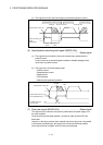
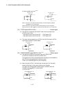
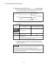
2) Servo amplifier input use
(Note-3)
FLS signal : ON FLS signal : OFF
FLS
DI1
DICOM
FLS
DI1
DICOM
MR-J3- B
MR-J3- B
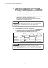
(Note-1): Refer to the "Q173HCPU/Q172HCPU Motion controller Programming Manual
(COMMON)" for an external signal.
(Note-2): Refer to the "Q173HCPU/Q172HCPU User’s Manual" for a pin configuration.
(Note-3): Refer to the "MR-J3-
B Servo Amplifier Instruction Manual" for a pin configuration.
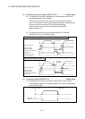
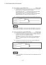
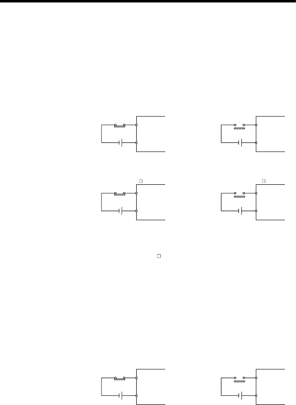
(13) RLS signal (M2412+20n)
(Note-1)
.................................. Status signal
(a) This signal is controlled by the ON/OFF state for the lower stroke limit
switch input (FLS) of the Q172LX/servo amplifier.
• Lower stroke limit switch input OFF ...... RLS signal: ON
• Lower stroke limit switch input ON ........ RLS signal: OFF
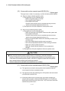
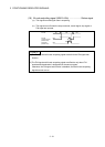
(b) The state of the lower stroke limit switch input (RLS) when the RLS signal is
ON/OFF is shown below.
1) Q172LX use
(Note-2)
RLS signal : ON
Q172LX
RLS
RLS
COM
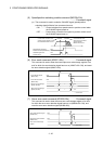
RLS signal : OFF
Q172LX
RLS
RLS
COM