4 - 14
4 PARAMETERS FOR POSITIONING CONTROL
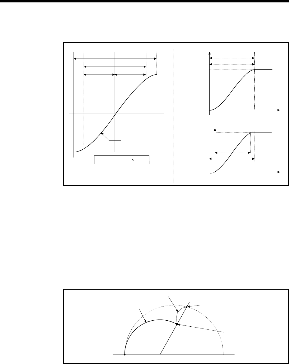
As shown below, the S-curve ratio setting serves to select the part of the sine curve to
be used as the acceleration/deceleration curve.
A
B
B/2 B/2
Sine curve
S-curve ratio = B/A 100[%]
A
B
Positioning speed
B/A=1.0
V
Positioning speed
V
A
B
B/A=0.7
S-curve ratio is 100[%]
S-curve ratio is 70[%]
4.3.3 Allowable error range for circular interpolation
The locus of the arc calculated from the start point address and central point address
may not coincide with the set end point address for the central-specified control.
The allowable error range for circular interpolation sets the allowable range for the error
between the locus of the arc determined by calculation and the end point address.
If the error is within the allowable range, circular interpolation to the set end point
address is executed while also executing error compensation by means of spiral
interpolation.
If it exceeds the setting range, an error occurs at the start and positioning does not
start. Such an error are set the applicable axis or minor error code area.
Locus determined by spiral
interpolation
Erro
End point address
by calculation
Setting end point
address
Start point address Central point address
Fig. 4.4 Spiral Interpolation
