


3 - 65
3 POSITIONING DEDICATED SIGNALS
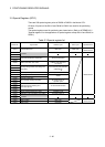
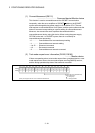
(10) Operation cycle of the Motion CPU setting (D9197)
........... Monitor device
The setting operation cycle is stored in [
µs
] unit.
When the "Automatic setting" is set in the system setting, the operation cycle
corresponding to the number of setting axes. When "0.4[ms] / 0.8[ms] / 1.7[ms] /
3.5[ms] / 7.1[ms] / 14.2[ms]" is set in the system setting, the operation cycle
corresponding to each setting.
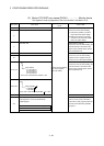
(Note): If the servo amplifiers of 9 axes or more are connected to one SSCNET
system, it does not support an operation cycle of 0.4[ms]. 0.8[ms] is used
as the real operation cycle, even if 0.4[ms] is set in the system setting.
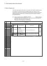
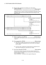
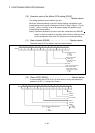
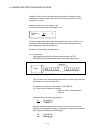
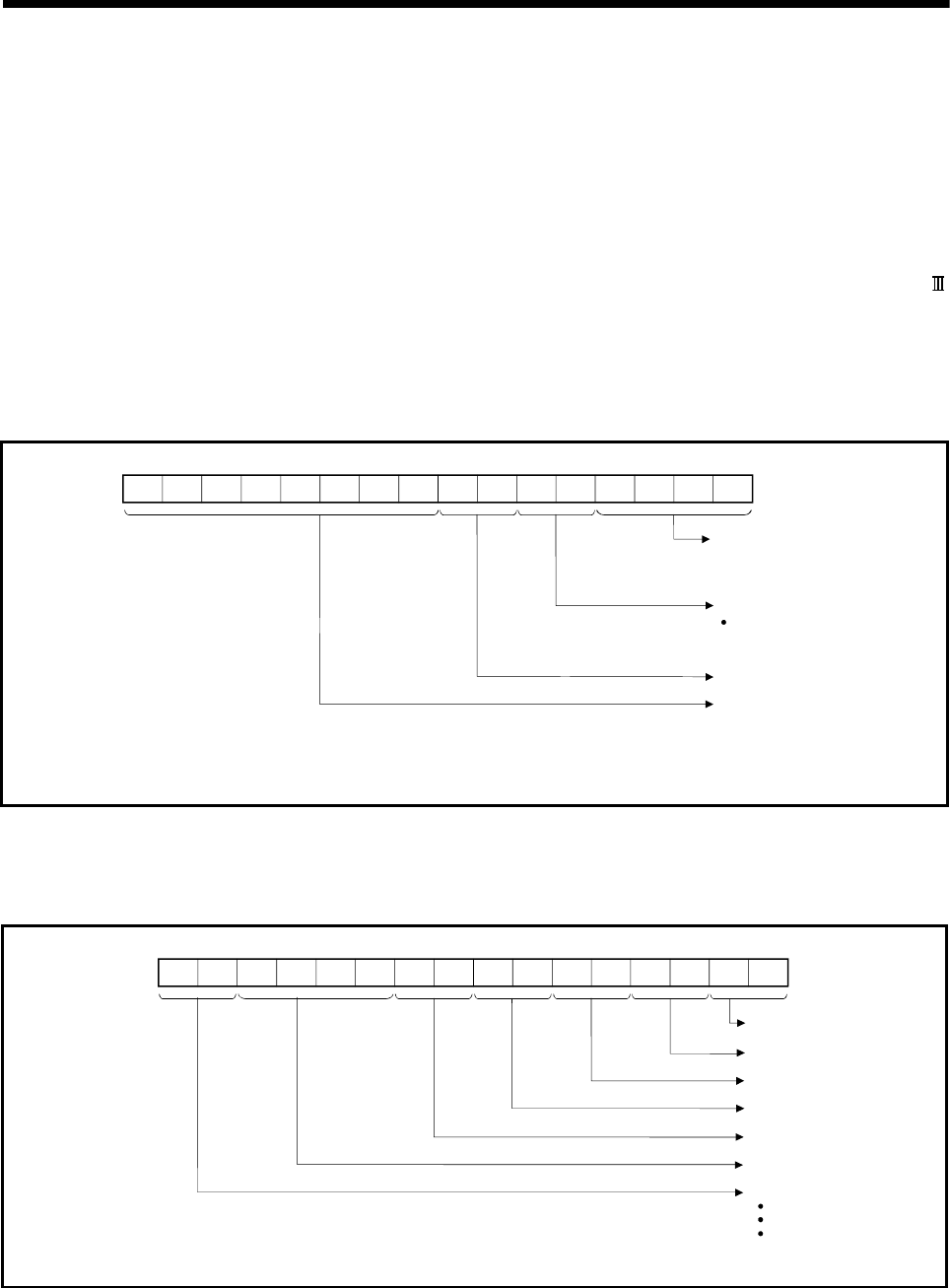
(11) State of switch (D9200) ………………………….. Monitor device
The switch state of CPU is stored in the form of the following.
Switch state of CPU
b15 b14 b13 b12 b11 b10 b9 b8 b7 b6 b5 b4 b3 b2 b1
Memory card switch
Always OFF
(All setting of each
digit is "0".)
b0
D9200
No used
0 : RUN
1 : STOP
2 : L.CLR
0 : OFF
1 : ON
b8 to b12 corresponds to
SW1 to SW5 of the
system setting switch.
(b13 to b15 : Not used)
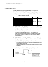
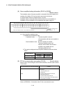
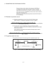
(12) State of LED (D9201)…………………………..…… Monitor device
It stores whether the LED of CPU is in which state in next by the following bit
patterns. 0 is OFF, 1 is ON and 2 is Flicker.)
RUN
b15 b14 b13 b12 b11 b10 b9 b8 b7 b6 b5 b4 b3 b2 b1 b0
D9201
ERROR
M.RUN
BAT.ALARM
BOOT
Not used
MODE
0 : OFF
1 : Green
2 : Orange
(Note): Indicate the following setting.
0 : OFF
1 : ON
2 : Flicker