


3 - 4
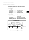
3 POSITIONING DEDICATED SIGNALS
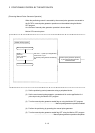
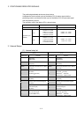
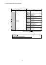
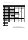
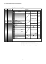
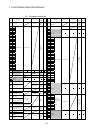
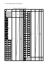
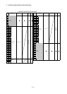
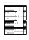
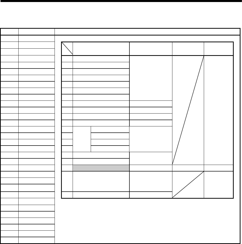
(2) Axis status list
Axis No. Device No. Signal name
1 M2400 to M2419
2 M2420 to M2439
3 M2440 to M2459
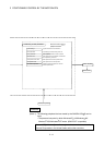
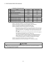
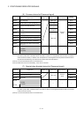
Signal name Refresh cycle Fetch cycle Signal direction
4 M2460 to M2479 0 Positioning start complete
5 M2480 to M2499 1 Positioning complete
6 M2500 to M2519 2 In-position
7 M2520 to M2539 3 Command in-position
8 M2540 to M2559 4 Speed controlling
9 M2560 to M2579 5 Speed/position switching latch
10 M2580 to M2599 6 Zero pass
Operation cycle
11 M2600 to M2619 7 Error detection Immediate
12 M2620 to M2639 8 Servo error detection Operation cycle
13 M2640 to M2659 9 Home position return request Main cycle
14 M2660 to M2679 10 Home position return complete Operation cycle
15 M2680 to M2699
11 FLS
16 M2700 to M2719 12 RLS
17 M2720 to M2739 13 STOP
18 M2740 to M2759 14
External
signals
DOG/CHANGE
Main cycle
19 M2760 to M2779 15 Servo ready
20 M2780 to M2799 16 Torque limiting
Operation cycle
Status signal
21 M2800 to M2819 17 Unusable — — —
22 M2820 to M2839
23 M2840 to M2859
24 M2860 to M2879
18
Virtual mode continuation
operation disable warning
signal (SV22)
(Note-1)
At virtual mode
transition
25 M2880 to M2899 19 M-code outputting signal Operation cycle
Status signal
26 M2900 to M2919
27 M2920 to M2939
28 M2940 to M2959
29 M2960 to M2979
30 M2980 to M2999
31 M3000 to M3019
32 M3020 to M3039
(Note-1): It is unusable in the SV13/SV22 real mode.
(Note-2): The range of axis No.1 to 8 is valid in the Q172HCPU.
(Note-3): Device area of 9 axes or more is unusable in the Q172HCPU.