


6 - 59
6 POSITIONING CONTROL
(1) The setting range of end point address for the both of circular interpolation axis
and linear interpolation axis is (-2
31
) to (2
31
-1).
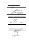
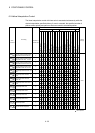
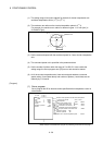
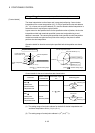
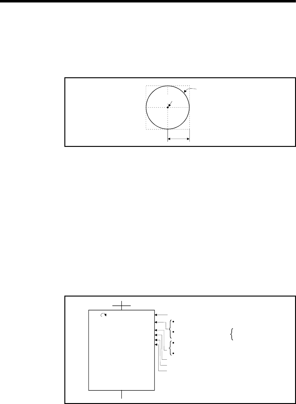
(2) The maximum arc radius on the circular interpolation plane is (2
31
-1).
For example, the maximum arc radius for electronic gear 1:1 of unit [mm] is
214748364.7[
µm].
Maximum arc
2
31
-1-2
31
2
31
-1
0
Radius R
Arc central point
(3) Set the command speed with the combined-speed for 2 axes circular interpolation
axis.
(4) The command speed unit is specified in the parameter block.
(5) Set the number of pitches within the range of 0 to 999. If it is set outside the
setting range, the servo program error [28] occurs, and cannot be started.
(6) All of the circular interpolation axis, linear axis and point address, command
speed, radius (2 word data above) and number of pitches (1 word data) are set
indirectly by D, W and #.
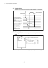
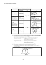
[Program]
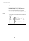
(1) Servo program
Servo program No.52 for absolute radius-specified helical interpolation control is
shown below.
<K 52>
ABH
Axis
Axis
Linear axis
Speed
Number of pitches
Radius
1,
2,
3,
100000
50000
25000
1000
100
60000
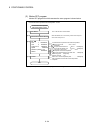
Axis for the circular . . . . . . . .
interpolation
End point address of the linear axis . . . . . 25000
Positioning speed . . . 1000
Number of pitches . . .
Radius on a circular interpolation plane . . . . . 60000
Axis 1 . . . 100000
Axis 2 . . . . 50000
Linear axis for the circular. . . . . . . . . . . . . Axis 3
interpolation and linear interpolation
End point address of the . . .
circular interpolation axis
100
Axis 1, Axis 2
Absolute radius specified-circular helical interpolation
(Note): Example of the Motion SFC program for positioning control is shown next page.