


3 - 46
3 POSITIONING DEDICATED SIGNALS
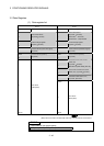
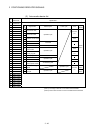
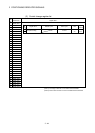
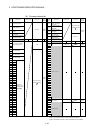
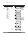
3.2.1 Axis monitor devices
The monitoring data area is used by the Motion CPU to store data such as the feed
current value during positioning control, the real current value and the number of
droop pulses in the deviation counter.
It can be used to check the positioning control state using the Motion SFC program.
The user cannot write data to the monitoring data area (except the travel value
change register).
Refer to APPENDIX 5 "Processing Time of the Motion CPU" for the delay time
between a positioning device (input, internal relay and special relay) turning on/off and
storage of data in the monitor data area.
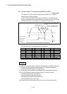
(1) Feed current value storage register (D0+20n, D1+20n)
....…….. Monitor device
(a) This register stores the target address output to the servo amplifier on the
basis of the positioning address/travel value specified with the servo
program.
1) A part for the amount of the travel value from "0" after starting is stored in
the fixed-pitch feed control.
2) The current value from address at the time of starting is stored in the
speed/position switching control.
However, the address at the time of starting varies depending on the
ON/OFF state of the feed current value update command (M3212+20n) at
the start.
• M3212+20n: OFF ..... Resets the feed current value to "0" at the start.
• M3212+20n: ON ..... Not reset the feed current value at the start.
3) "0" is stored during speed control.
(b) The stroke range check is performed on this feed current value data.
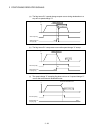
(2) Real current value storage register (D2+20n, D3+20n)
....…….. Monitor device
(a) This register stores the real current value which took the droop pulses of the
servo amplifier into consideration to the feed current value.
(b) The "feed current value" is equal to the "real current value" in the stopped
state.
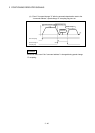
(3) Deviation counter value storage register (D4+20n, D5+20n)
....…….. Monitor device
This register stores the droop pulses read from the servo amplifier.
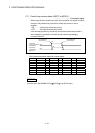
(4) Minor error code storage register (D6+20n) ............. Monitor device
(a) This register stores the corresponding error code (Refer to APPENDIX 1.2)
at the minor error occurrence. If another minor error occurs after error code
storing, the previous error code is overwritten by the new error code.
(b) Minor error codes can be cleared by an error reset command (M3207+20n).